
Multi-view integrated camera system

Active Publication Date: 2006-02-02
MICROSOFT TECH LICENSING LLC
View PDF72 Cites 63 Cited by
  • Summary
  • Abstract
  • Description
  • Claims
  • Application Information

AI Technical Summary

Benefits of technology

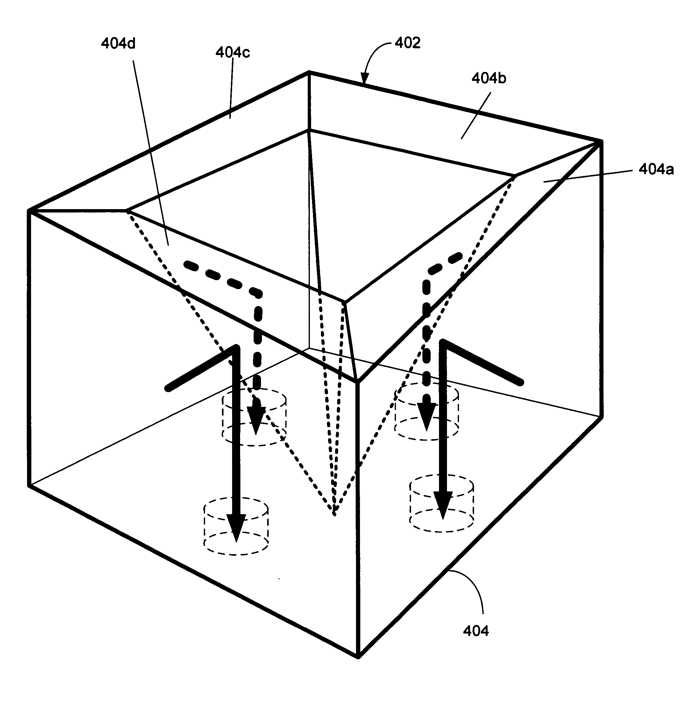
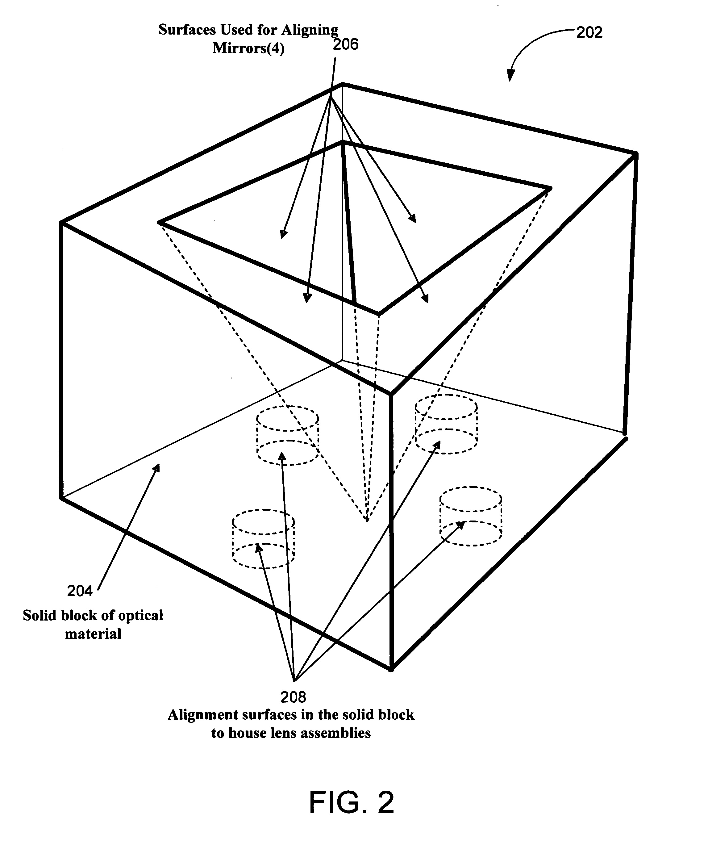
[0006] The invention is directed towards a camera design and process that overcomes the aforementioned limitations in videoconferencing cameras by employing a panoramic camera design that is lower cost, robust, stable and more user friendly than prior art designs. The camera design of the present invention makes use of a unified molded structure made of optical material to house a mirror, aligned sensor, and lens assembly. The unified molded structure of the camera keeps the sensed optical path enclosed to minimize dust and user's fingers and maintain optical alignment.
[0009] In another embodiment of the invention the cameras of the camera array have an up look angle to have a more usable vertical field of view as is described in the aforementioned co-pending patent application to image more of the meeting participants and less of the conferencing table. This configuration maximizes the use of the imaging sensors, further reducing cost of the system. More specifically, cameras with a smaller vertical field of view can be used as almost the entire field of view captures the video conference participants' faces and not extraneous data such as the surface the camera is sitting on. The up look angle can be implemented by tilting each camera (e.g., each lens sensor pair) as is described in the co-pending application. However, the upward tilt angle can also be implemented by having a prism on the external (vertical) surface or the internal (horizontal) surface of the optical block housing. This second method of obtaining the up look angle allows the camera sensors to be mounted flat on a Printed Circuit Board (PCB), which reduces complexity, cost, and calibrations. Some chromatic aberration is induced (on the order of a pixel width), but this can be corrected via image processing.
[0011] In yet another embodiment of the camera design of the present invention the optical block housing is not of unitary design. The housing is similar to that previously described but is assembled from sections of optical material. This design can be easier to fabricate.

Problems solved by technology

Video conferencing systems have had limited commercial success.
In many cases video conferencing systems are too expensive for individuals and small businesses to afford.
Additionally, there are numerous technical deficiencies in the video conferencing systems to date.
Poor camera viewpoints and insufficient image resolution make it difficult for meeting participants to see the person speaking.
This is compounded by the fact that many camera systems are difficult for the user to operate.
Cameras for video conferencing systems are sometimes very delicate and can be damaged by an untrained user trying to adjust the camera system.
Although advances have been made in camera designs for video conferencing, especially in the area of using panoramic camera designs, these designs are often expensive, fragile, unstable and not very user friendly.
Prior art designs do not have these pieces integrated into a unified structure such as a block, and hence are fragile and difficult to align.

Method used


Image

  • Multi-view integrated camera system
  • Multi-view integrated camera system
  • Multi-view integrated camera system

Examples


Embodiment Construction

[0024] In the following description of the preferred embodiments of the present invention, reference is made to the accompanying drawings that form a part hereof, and in which is shown by way of illustration specific embodiments in which the invention may be practiced. It is understood that other embodiments may be utilized and structural changes may be made without departing from the scope of the present invention.

1.0 Exemplary Operating Environment

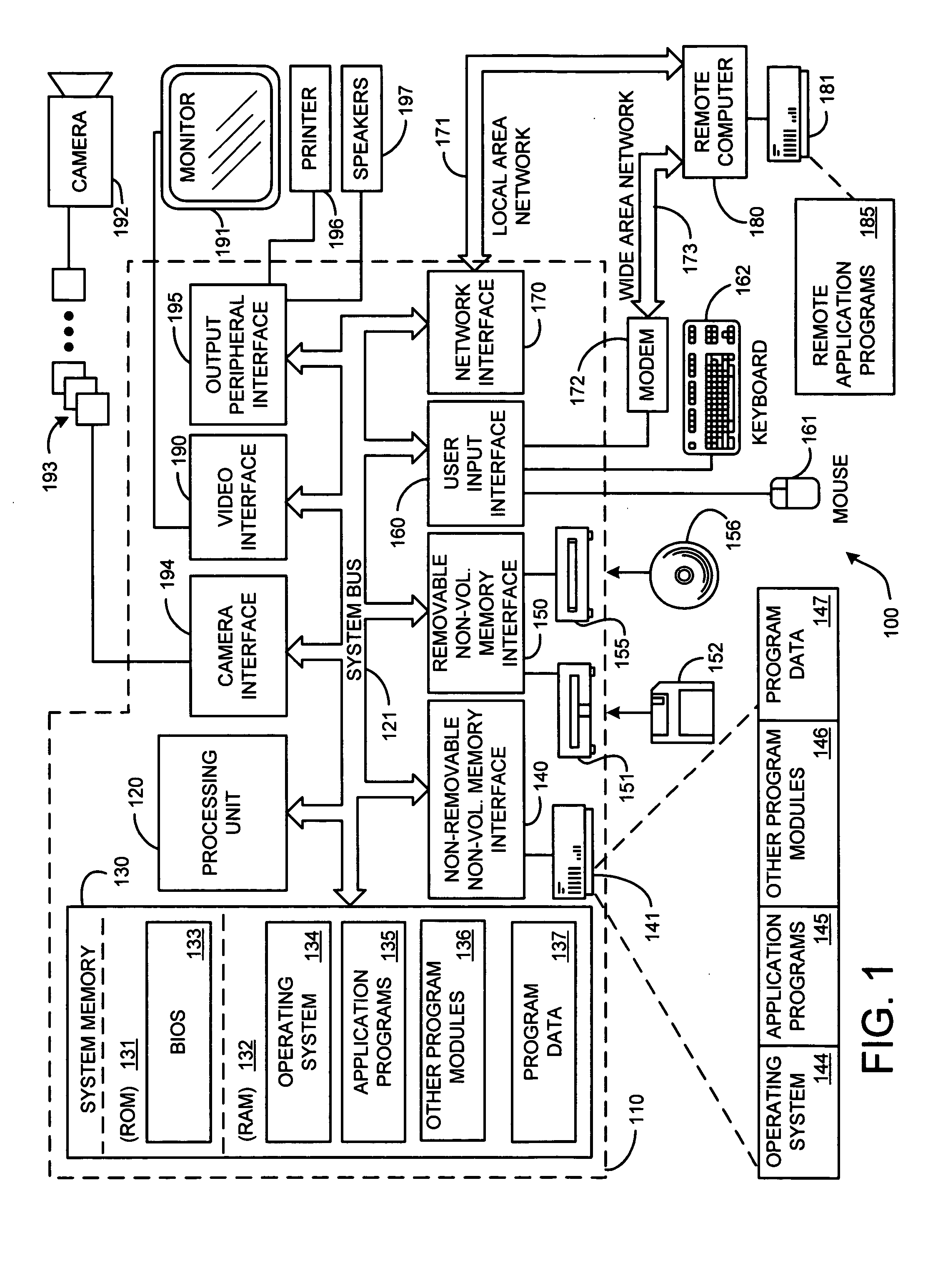
[0025]FIG. 1 illustrates an example of a suitable computing system environment 100 on which the invention may be implemented. The computing system environment 100 is only one example of a suitable computing environment and is not intended to suggest any limitation as to the scope of use or functionality of the invention. Neither should the computing environment 100 be interpreted as having any dependency or requirement relating to any one or combination of components illustrated in the exemplary operating environment 100.

[0026] The i...


PUM


Abstract

A panoramic camera design that is lower cost, robust, stable and more user friendly than prior art designs. The camera design makes use of a unified molded structure of optical material to house a mirror, aligned sensor, and lens assembly. The unified molded structure of the camera keeps the sensed optical path enclosed to minimize dust and user's fingers and maintain optical alignment.

Description

BACKGROUND [0001] 1. Technical Field [0002] This invention is directed toward a new camera design. More specifically, this invention is directed toward a new omni-directional camera design that makes use of a unified molded structure of optical material to house a mirror, aligned sensor, and lens assembly. [0003] 2. Background Art [0004] Video conferencing systems have had limited commercial success. This is due to many factors. In many cases video conferencing systems are too expensive for individuals and small businesses to afford. Additionally, there are numerous technical deficiencies in the video conferencing systems to date. Poor camera viewpoints and insufficient image resolution make it difficult for meeting participants to see the person speaking. This is compounded by the fact that many camera systems are difficult for the user to operate. Cameras for video conferencing systems are sometimes very delicate and can be damaged by an untrained user trying to adjust the camera ...

Claims


Application Information

Patent Timeline
IPC IPC(8): G02B13/16
CPCG02B27/2228G03B37/04H04N5/247G03B17/17G02B30/34H04N23/90
Inventor YEE, DAWSONCUTLER, ROSS
Owner MICROSOFT TECH LICENSING LLC
Learn More