
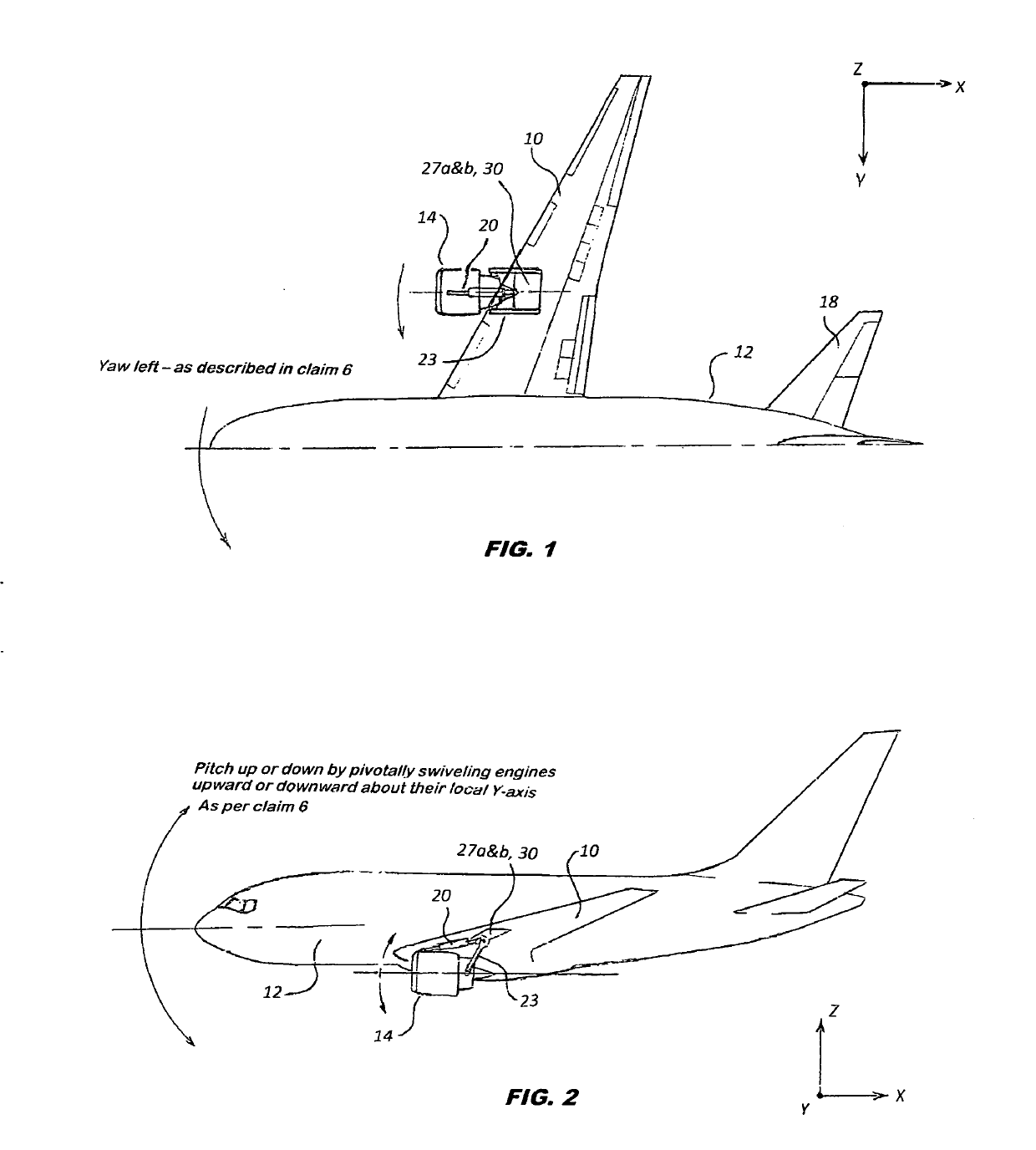
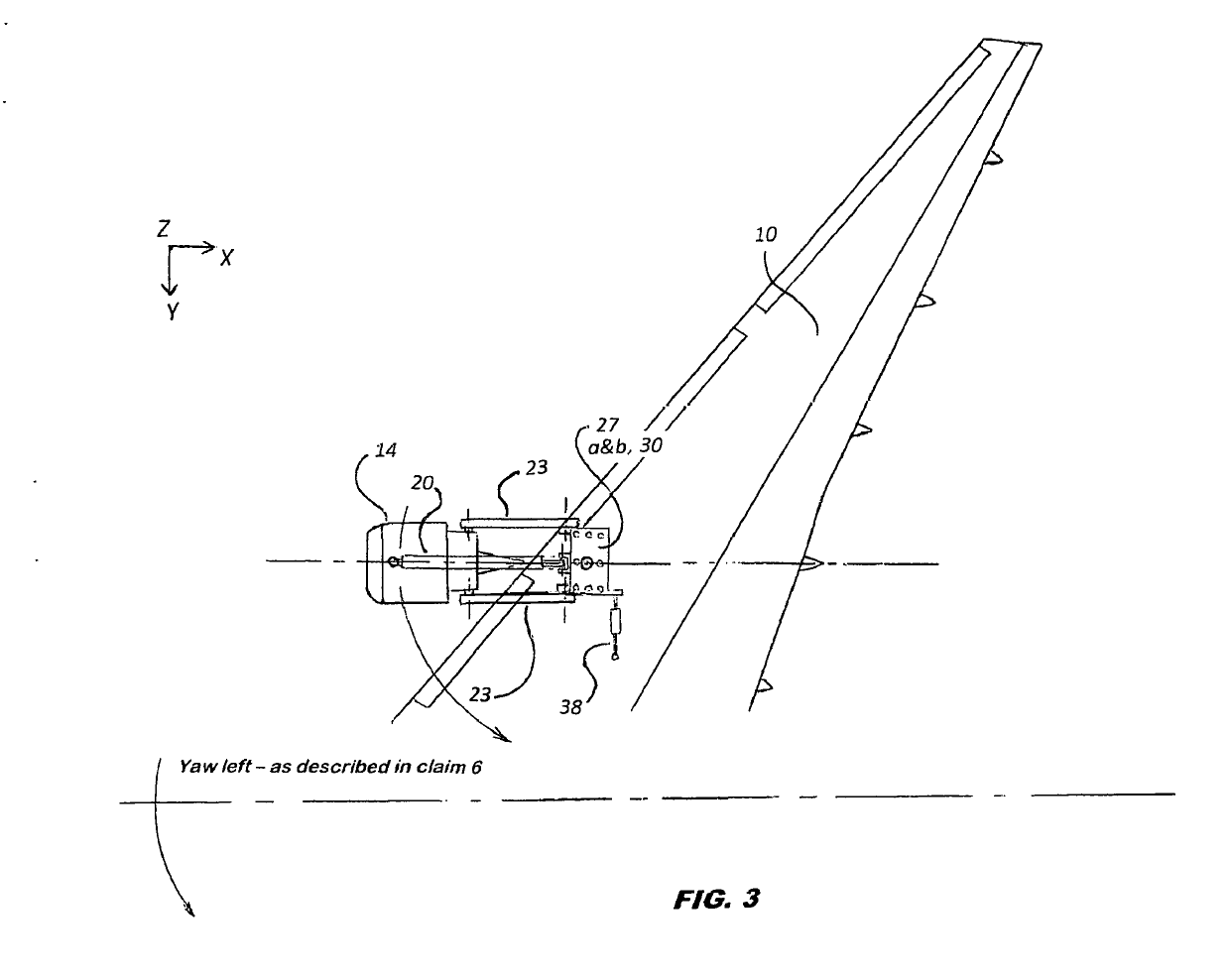
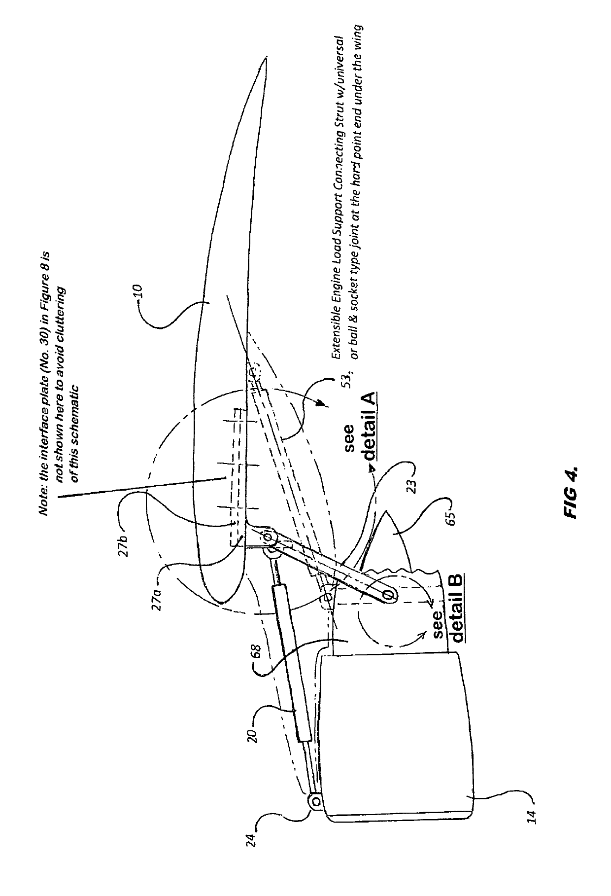
Under the wing-mounted jet engine with pivotal swivel joint to produce directional thrust vectoring thru swivel angle

a technology of swivel angle and pivotal swivel joint, which is applied in the direction of power plant arrangement/mounting, aircraft navigation control, transportation and packaging, etc., can solve the problems of complexities of such tilting mechanism, lack of moderate to agile maneuverability in takeoff, landing, roll and yaw motion, etc., and achieve the effect of further controlling the flight position of the jet aircra

Active Publication Date: 2019-06-06
FOTOUHIE HADIE
View PDF21 Cites 9 Cited by
  • Summary
  • Abstract
  • Description
  • Claims
  • Application Information

AI Technical Summary

Benefits of technology

The patent text talks about a way to control the direction of exhaust gases from jet engines to improve the there (attitude) of a jet aircraft during flight. This is called TVC (thrust vectoring control) and it is commonly used in military jet aircrafts for short distance landing and takeoff. The technical effect of this control is to enhance the performance and stability of the jet aircraft during flight.

Problems solved by technology

Today, still one of the major problems encountered in civil aviation which for the most part utilizes jet aircraft with 2 or 4 under wing-mounted engines is the lack of moderate to agile maneuverability in takeoff, landing (ascend and descend), roll and yaw motions.
Also, the tiltrotor aircrafts use thrust vectoring by rotating the turboprop engine nacelles, although there have been complexities in such tilting mechanisms.
For example, one patent (granted to airbus industries) is limited to rear fuselage mounted jet engine aircrafts.

Method used


Image

  • Under the wing-mounted jet engine with pivotal swivel joint to produce directional thrust vectoring thru swivel angle
  • Under the wing-mounted jet engine with pivotal swivel joint to produce directional thrust vectoring thru swivel angle
  • Under the wing-mounted jet engine with pivotal swivel joint to produce directional thrust vectoring thru swivel angle

Examples


Embodiment Construction

[0020]It is particularly important to be able to further control the pitch (movement of nose up or down of an aircraft) during ascend, descend, takeoff and landing, the roll (movement of an aircraft banking to the left or right), and the yaw (movement of an aircraft sideways to the right or left) of a large commercial jet aircraft with 2 or 4 engines mounted under its wings, during flight in a more agile and efficient way over a shorter air traveled distance, which at times can cause avoiding catastrophes such as mid-air collision or to avoid missing a desired flight path which can be caused by lack of adequate control over short distance by merely relying on the traditional wing or tail section aerodynamic control surfaces.

[0021]In this claim first of all the intended user is the normally larger commercial jetliners with 2 or 4 jet engines mounted under their wings, and secondly instead of using thrust reversers or by using rotating jet nozzles to tilt the exhaust gases upward or d...


PUM


Abstract

In the so called internal combustion (reaction type) airbreathing jet engines (including turbojets and turbofans) fast moving discharging combustion exhaust gases from core exhaust stream and air will generate jet propulsion. In other words, the produced thrust thru an exit nozzle in such engines moves the jet aircraft forward in flight.During flight of a jet aircraft the essential steering movements (roll, pitch and yaw type maneuvers) are normally performed via control surfaces on its wings and its tail sections. These controls are activated by pilot from inside the cabin.This invention allows for swiveling of a pivotable jet engine mounted under the wings of a commercial jet aircraft, to direct exhaust gases (combustion gases and bypass airflow in case of turbofan engines and in general the engine core exhaust gases for turbojets) upward or downward or sideways (outboard of the cabin and the fuselage) to some limited extent to achieve more agile air maneuvers compared to the traditional fixed under the wing-mounted jet engines. The restricted hinged swivel angular motion of the engine(s) pivotally mounted under the wings of such a jet aircraft will make it possible for comfortably (and not abruptly) shortening the required air distance needed to perform aircraft's attitude adjustment maneuvers needed such as during descent, takeoff, landing approach or during cruise to control flightpath and / or quickly avoid air traffic potential problems.Therefore, the idea of performing agile maneuvers “which at times can become critical in the flight safety of especially larger passenger jetliners” is realized by swiveling jet engines under the wings of a 2 or 4 engine commercial jet aircraft about a pivot point mounted along the engine nacelle to enable highly efficient pitch and roll motions in flight (with enhanced agility), as well as making efficient and agile yaw type motion in flight by turning the entire / plurality of engine assembly (away from the fuselage / cabin) around a central point underneath the wing assembly.

Description

BACKGROUND OF THE INVENTION[0001]Today, still one of the major problems encountered in civil aviation which for the most part utilizes jet aircraft with 2 or 4 under wing-mounted engines is the lack of moderate to agile maneuverability in takeoff, landing (ascend and descend), roll and yaw motions.[0002]Such problem in modern military jets in service has been addressed by using TVC or thrust vectoring control to facilitate enhanced maneuvers in air and especially for short takeoff and landing.[0003]The current state of technology built into modern fighter jet aircrafts uses thrust vectoring technique to divert the exhaust jet stream upward or downward for better agility of such jet aircrafts during takeoff and landing. In recent years turbofan engines with rotating nozzles have also been invented capable of deflecting their exhaust gas streams. In VTOL type military jet aircrafts, the deflection has been up to 90 degrees relative to the centerline of the aircraft (X-axis) which has ...

Claims


Application Information

Patent Timeline
IPC IPC(8): B64C15/12B64D27/18B64D27/26
CPCB64C15/12B64D27/18B64D27/26B64D2027/262B64D27/406B64D27/404B64D27/40
Inventor FOTOUHIE, HADIE
Owner FOTOUHIE HADIE
Learn More