Pneumatic rotary tool with airway switching structure

Inactive Publication Date: 2019-05-30
DE POAN PNEUMATIC
View PDF5 Cites 3 Cited by
  • Summary
  • Abstract
  • Description
  • Claims
  • Application Information

AI Technical Summary

Benefits of technology

The present invention provides a pneumatic tool with a dial ring located at the rear end of the tool. This dial ring is located adjacent to the air inlet of the tool, making it easy for the user to turn it. This allows for easier switching between forward and reverse rotational modes, making it easier to screw or unscrew nuts or bolts. Overall, this design solves the inconvenience of tools that have dial rings located close to their drive lugs.

Problems solved by technology

Due to the dial ring 50a being located close to the drive lug, while a user conducts an operation, such as screwing / unscrewing nuts or bolts, it is inconvenient for the user to turn the dial ring for switching the operation mode of the pneumatic rotary tool.
More specifically, while a user is operating the pneumatic tool at a narrow space, such as the chassis of a vehicle, for screwing / unscrewing nuts or bolts, the narrow space may cause the user inconvenience of turning the dial ring for switching the operational mode of the tool.

Method used


Image

  • Pneumatic rotary tool with airway switching structure
  • Pneumatic rotary tool with airway switching structure
  • Pneumatic rotary tool with airway switching structure

Examples


Embodiment Construction

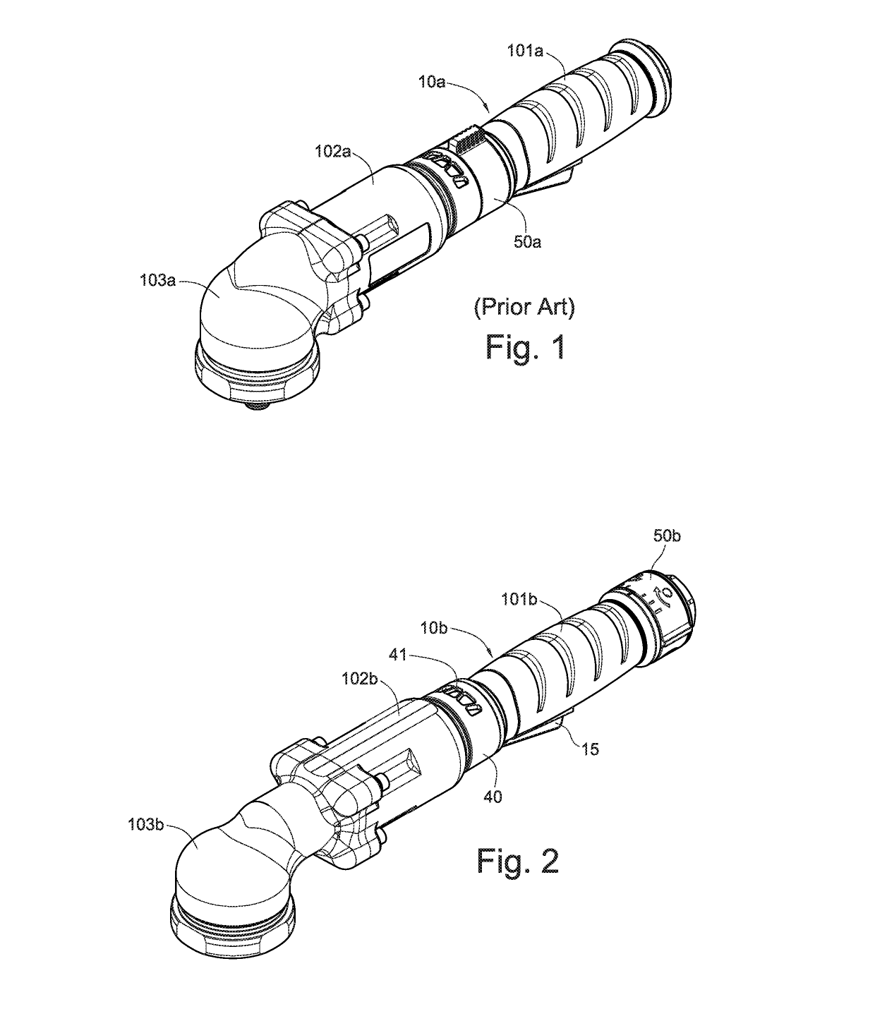
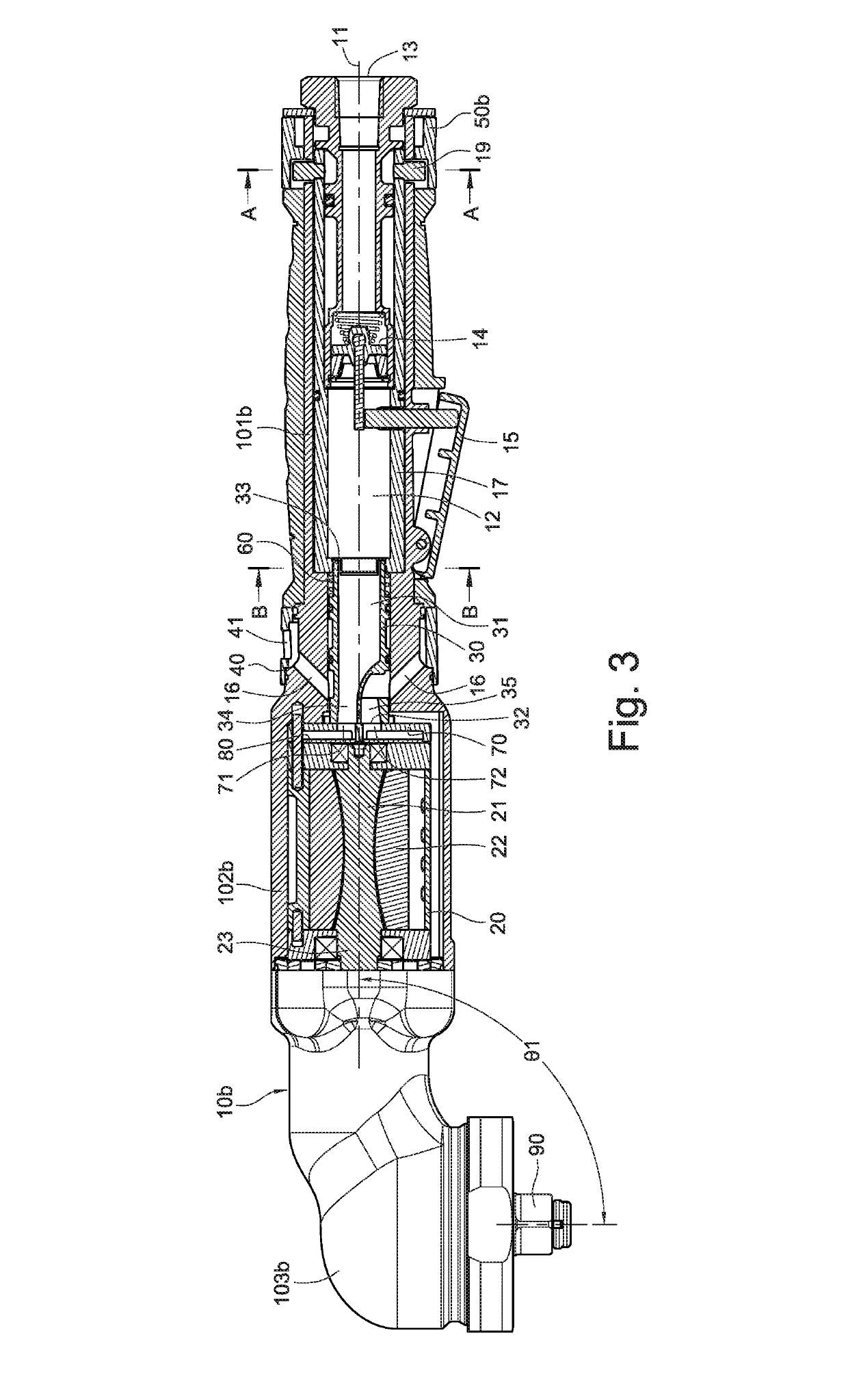
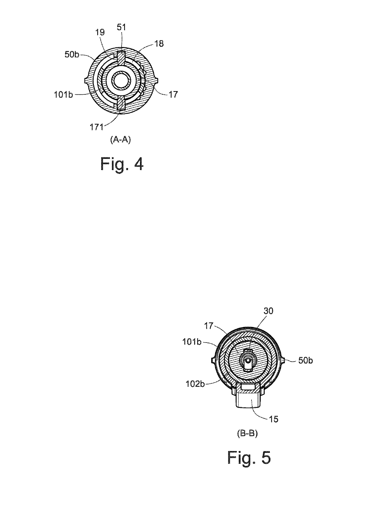
[0025]Referring to FIG. 2 through FIG. 5, a pneumatic rotary tool with an airway switching structure according to a first embodiment of the present invention is shown, which generally comprises a housing 10b, an air motor 20, a rotatable valve 30, and a dial ring 50b.

[0026]As shown in FIGS. 2 and 3, the housing 10b is cylindrical in shape and extends along a longitudinal axis 11, which allows the tool to be grasped more easily by hand. In practice, to facilitate installing the air motor 20 and the rotatable valve 30, the housing 10b can be constructed of a grip shell 101b, a motor shell 102b, and a head shell 103b, which are formed into an integral piece along the longitudinal axis 11 such that an air chamber 12 is defined in the grip shell 101b for receiving compressed or pressurized air, and an air inlet 13 is located at the grip shell 101b distal from the motor shell 102b in which the air motor 20 is installed. The air inlet 13 is located at the rear end of the pneumatic rotary ...


PUM


Abstract

A pneumatic rotary tool generally includes a housing, an air motor, a rotatable valve, and a dial ring. The housing defines therein an air chamber for receiving compressed air and is furnished with a drive lug at one end and an air inlet at an opposite end, wherein the air inlet communicates with the air chamber. The air motor is disposed in the housing between the drive lug and the air chamber and has an output shaft connected to the drive lug. The rotatable valve is rotatably disposed in the housing between the air motor and the air chamber. The dial ring is rotatably mounted around the housing, close to the air inlet, and coupled to the rotatable valve by a tube therebetween to enable the air motor to be switched between a forward rotation mode and a reverse rotation mode.

Description

(a) TECHNICAL FIELD OF THE INVENTION[0001]The present invention relates to a pneumatic rotary tool for screwing / unscrewing objects and, more particularly, to a pneumatic rotary tool with an airway switching structure.(b) DESCRIPTION OF THE PRIOR ART[0002]Pneumatic rotary tools are generally used to provide operators with the function of screwing and unscrewing bolts or nuts. The tool is usually provided with an air motor which receives compressed air to produce rotational kinetic energy output. Generally, the rotational kinetic energy is produced together with impact kinetic energy, so that nuts or bolts can be screwed more tightly or unscrewed more quickly[0003]To screw / unscrew nuts or bolts, a pneumatic rotary tool should have the capability of conducting forward rotation and reverse rotation, and this relies on the compressed air received in the tool to have the air motor conduct the forward / reverse rotation, and the tools configured with airways corresponding to the forward rota...

Claims


Application Information

Patent Timeline
IPC IPC(8): B25F5/00B25B21/02B25F5/02
CPCB25F5/001B25B21/02B25F5/02B25B21/00
Inventor WU, I-TSUNGWEN, YI-WEIYANG, SHUN-YAO
Owner DE POAN PNEUMATIC
Why Eureka
Try Eureka