Low-radiation interference, high-efficiency, high-linearity, and high-robustness power tube driver of class-d audio amplifier

a power tube driver and amplifier technology, applied in the field of audio amplifiers, can solve the problems of radiation interference sacrificing efficiency and linearity, linearity and robustness, and the use of fixed gate charge speed and rc delay to generate fixed dead time cannot meet the above four aspects very well, so as to reduce radiation interference, improve efficiency and linearity, and reduce the effect of radiation interferen

Active Publication Date: 2019-05-16
SI EN TECH XIAMEN
View PDF0 Cites 1 Cited by
  • Summary
  • Abstract
  • Description
  • Claims
  • Application Information

AI Technical Summary

Benefits of technology

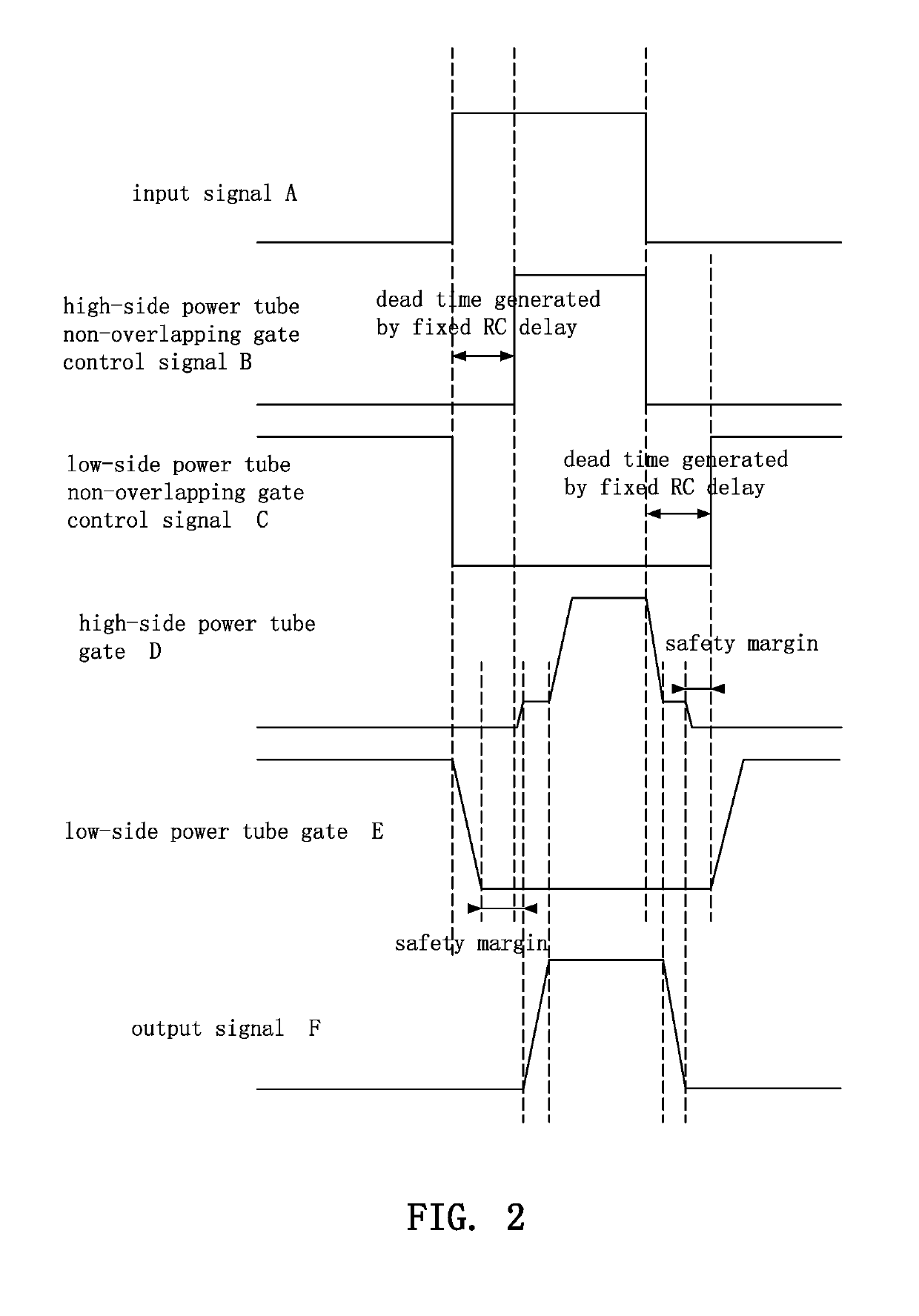
[0025]1. In this disclosure, a novel “Detection-Segmentation Charge / Discharge” method for controlling the speed of the gate charge / discharge (charging when the power tube is turned on, and discharging when the power tube is turned off) is designed. At different power tube charge / discharge stages, different charge / discharge speeds are provided respectively. In a charge / discharge stage without affecting the radiation interference, a quick charge / discharge is provided to guarantee high efficiency and linearity. At a charge / discharge stage affecting the radiation interference (or the power tube has a voltage falling within the vicinity of the threshold voltage), a slow charge / discharge is provided to reduce the radiation interference. In the conventional fixed gate charge method, if the radiation interference is reduced, it will be necessary to slow down the whole charge / discharge process, and thus the efficiency and linearity will be lowered significantly.
[0026]2. In this disclosure, a “Detection-Cross Feedback” dead time control method is adopted. When the power tube switches and changes its operation, the power tube gate voltage on the side to be shutdown is detected first to assure that the gate voltage is lower than the threshold voltage. After such gate voltage is confirmed to be shutdown, the power tube on the other side is turned on. Such arrangement makes sure that both high- and low-side power tubes will not be electrically conducted at the same time (so as to guarantee the high robustness) without producing additional dead time, so that the linearity will not be affected adversely. In the conventional way of producing dead time by the RC delay, there are no detection and feedback structures, the required precise gate discharge time is not known, so that the design usually adds a safety margin for the prediction of the gate discharge time to guarantee the high robustness. However, the existence of the safety margin affects the linearity of the amplifier adversely. In the novel design of this disclosure, a precise gate discharge time can be obtained to complete the signal without requiring any safety margin at all. This disclosure not just improves the linearity only, but also guarantees the high robustness.

Problems solved by technology

The class-D amplifier is a switching amplifier which has an issue of large radiation interference in high-efficiency applications and also encounters more challenges in linearity and robustness than the traditional class-AB amplifiers.
Previous structural designs using a fixed gate charge speed and a RC delay to generate a fixed dead time are unable to satisfy the aforementioned four aspects very well.
1. Emphasis on low radiation interference may sacrifice efficiency and linearity.
2. Emphasis on high linearity may sacrifice radiation interference and robustness.
Since it is unable to estimate the required delay accurately, a considerable safety margin is required for the design of the RC time to guarantee the appropriate robustness and the linearity of the amplifier and prevent damages.
Since the conventional design adopts constant charge / discharge strength, a decrease of charge / discharge strength slows down the whole charge / discharge process and results in a significant drop of efficiency and linearity.
As the complexity of electronic systems becomes higher and higher, the radiation interference requirement becomes stricter, and the conventional design of the power tube driver no longer satisfy the requirements.
To meet the radiation interference requirement, the conventional design has to sacrifice other features and becomes unacceptable.

Method used


Image

  • Low-radiation interference, high-efficiency, high-linearity, and high-robustness power tube driver of class-d audio amplifier
  • Low-radiation interference, high-efficiency, high-linearity, and high-robustness power tube driver of class-d audio amplifier
  • Low-radiation interference, high-efficiency, high-linearity, and high-robustness power tube driver of class-d audio amplifier

Examples


Embodiment Construction

[0035]To understand the technical characteristics of this disclosure intuitively and comprehensively, exemplary embodiments are used and illustrated in referenced figures of the drawings. It is intended that the embodiments and figures disclosed herein are to be considered illustrative rather than restrictive.

[0036]With reference to FIG. 3 for a low-radiation interference, high-efficiency, high-linearity, and high-robustness power tube driver of a class-D audio amplifier in accordance with this disclosure, the power tube driver comprises a dead time generation circuit based on a gate voltage detection 1, a high-side fixed charge / discharge gate driving circuit 2, a low-side fixed charge / discharge gate driving circuit 3, a high-side gate charge / discharge accelerating circuit 4, a high-side gate voltage detection circuit 5, a low-side gate charge / discharge accelerating circuit 6, a low-side gate voltage detection circuit 7, a high-side power tube Q1, and a low-side power tube Q2.

[0037]...


PUM


Abstract

A power tube driver of a class-D audio amplifier includes high-side and low-side fixed charge/discharge gate driving circuits, high-side and low-side power tubes, a dead time generation circuit based on gate voltage detection, high-side and low-side gate charge/discharge accelerating circuits, and high-side and low-side gate voltage detection circuits. The class-D audio amplifier with the features of low radiation interference, and high efficiency, linearity and robustness can be balanced easily.

Description

BACKGROUND OF THE INVENTION1. Field of the Invention[0001]The present disclosure relates to an audio amplifier, in particular to a power tube driver of a class-D audio amplifier.2. Description of the Prior Art[0002]In the last decade, class-D amplifiers with the feature of high efficiency gradually replaced the traditional class-AB amplifiers and became increasingly popular in the audio application of portable devices such as mobile phones, tablet PCs, etc. In the last few years, the class-D amplifier started its application in the area of motor vehicles.[0003]The class-D amplifier is a switching amplifier which has an issue of large radiation interference in high-efficiency applications and also encounters more challenges in linearity and robustness than the traditional class-AB amplifiers.[0004]Power tube driver is a core module of the class-D amplifier and its structural design determines the radiation interference, efficiency, linearity and robustness of the class-D amplifier. P...

Claims


Application Information

Patent Timeline
Patent Type & Authority Applications(United States)
IPC IPC(8): H03F3/72H03F1/04H03F3/58H03F3/217
CPCH03F1/02H03F1/26H03F1/32H03F1/56H03F3/2178H03F3/2171H03F1/04H03F3/217H03F3/58H03F3/72H03F2200/78
Inventor YE, CHUNHUI
Owner SI EN TECH XIAMEN
Why Eureka
Try Eureka