
Terminal-equipped wire and method for crimping terminal onto wire

Active Publication Date: 2019-05-09
AUTONETWORKS TECH LTD +2
View PDF6 Cites 4 Cited by
  • Summary
  • Abstract
  • Description
  • Claims
  • Application Information

AI Technical Summary

Benefits of technology

This patent describes a device that prevents electrolytic corrosion in wire barrels by using a core tip and a core confirmation opening. The core tip prevents corrosion at the front edge of the wire barrel, and the core confirmation opening ensures that the core is securely fixed and does not excessively stress the barrel pieces. Overall, this device improves the reliability and performance of wire barrels.

Problems solved by technology

If moisture is present between contact parts of these two metals, both metals are dissolved in the form of ions into the moisture, and electrolytic corrosion occurs to corrode base metals by an electrochemical reaction.
When caulking the wire barrel to the core of the aluminum wire, the core may be exposed excessively long due to an error in an end processing (stripping) of the aluminum wire or the tip of the core may project more than necessary from the front edge of the caulked wire barrel due to a position error or the like when the core is placed on a bottom plate of the wire barrel.
As a result, a possibility of electrolytic corrosion due to the presence of the moisture remains.
However, if this is done, whether or not a necessary caulking length is ensured, i.e. whether or not a necessary fixing force is secured cannot be confirmed.
Thus, this measure cannot be adopted.

Method used


Image

  • Terminal-equipped wire and method for crimping terminal onto wire
  • Terminal-equipped wire and method for crimping terminal onto wire
  • Terminal-equipped wire and method for crimping terminal onto wire

Examples


Embodiment Construction

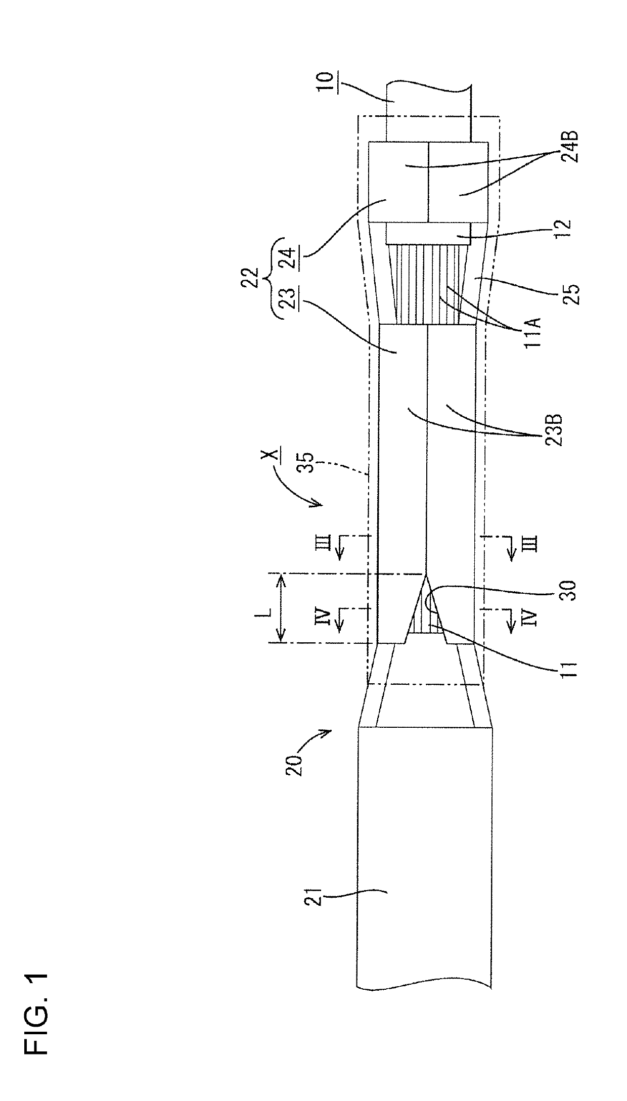
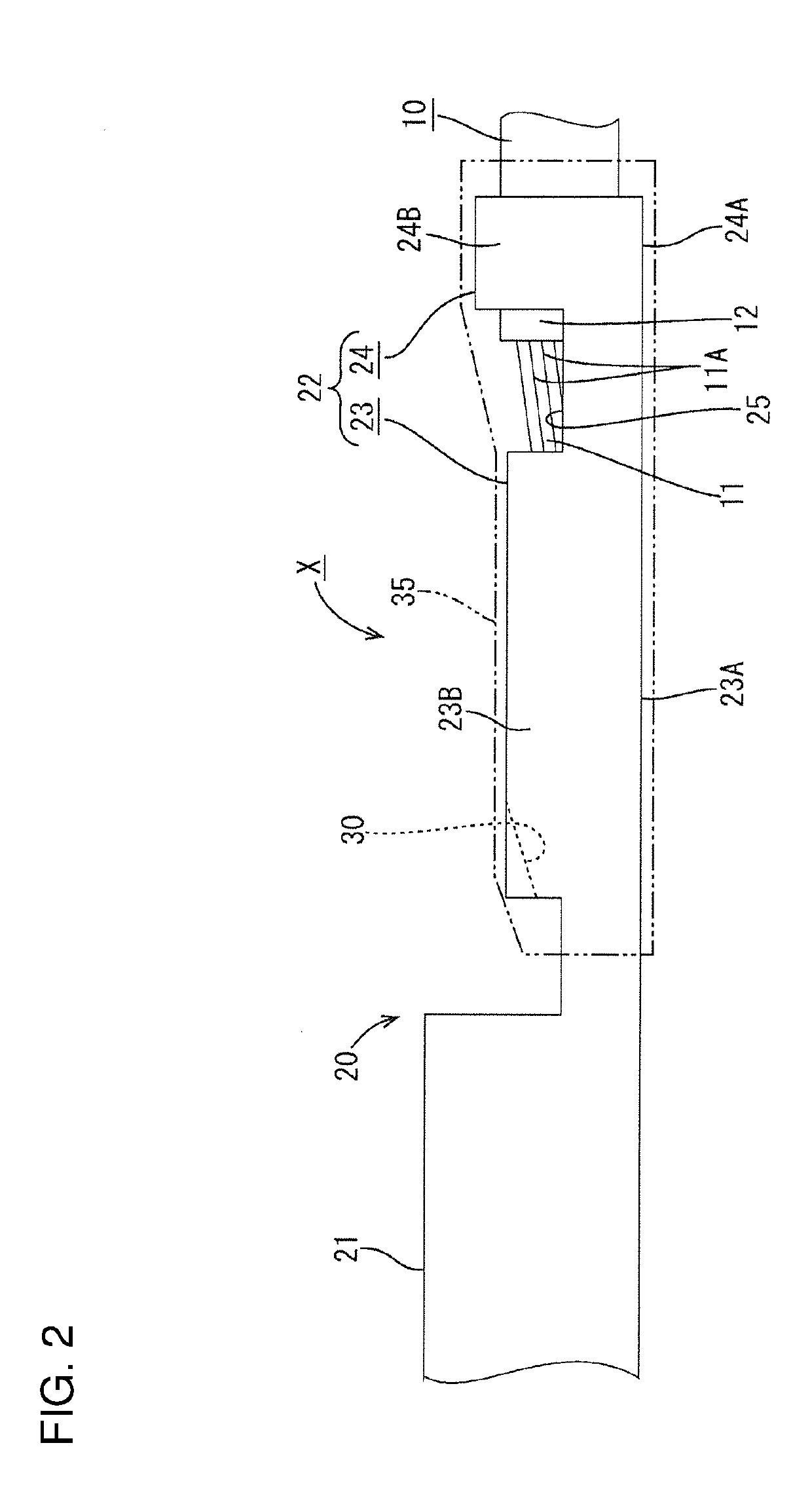
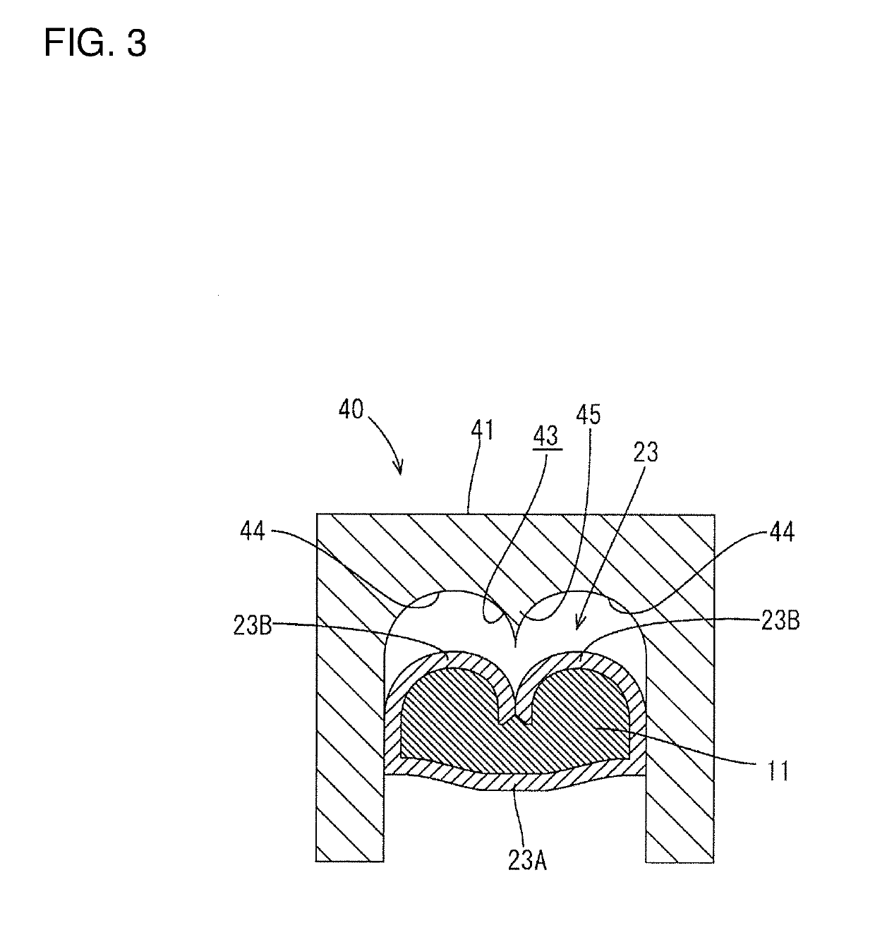
[0019]An embodiment is described with reference to FIGS. 1 to 4. A terminal-equipped wire X of this embodiment is configured such that a female terminal 20 is conductively connected to an end of an aluminum wire 10. An anticorrosive 35 is attached (applied) to cover around a wire connecting portion 22 in this female terminal 20.

[0020]As shown in FIGS. 1 and 2, the aluminum wire 10 is a coated wire and is structured such that the outer periphery of a core 11 formed by bundling a plurality of metal strands 11A made of aluminum or aluminum alloy is covered with an insulation coating 12 made of synthetic resin.

[0021]In connecting the female terminal 20 to the aluminum wire 10, an end processing is performed for removing (stripping) an end of the insulation coating 12 a predetermined length to expose the core 11 on an end of the aluminum wire 10.

[0022]The female terminal 20 is formed by press-working a base material made of copper or copper alloy and is structured such that a wire connec...


PUM


Abstract

A terminal-equipped wire (X) includes a wire (10) with a core (11) covered by with insulation coating (12). A terminal (20) including a wire barrel (23) is crimped onto the core (11) exposed at an end of the wire (10). An anticorrosive (35) is attached to cover the crimped wire barrel (23). The wire barrel (23) has barrel pieces (23B) extending from side edges of a bottom plate. The core (11) is placed on the bottom plate so that a tip of the core (11) is retracted rearwardly of front edges of the barrel pieces (23B) and the barrel pieces (23B) are crimped to embrace the core (11) while extending ends of the barrel pieces (23B) butt against each other. A core confirmation opening (30) is formed in a front of the crimped wire barrel (23) by widening an interval between corresponding butting parts of the barrel pieces (23B).

Description

BACKGROUNDField of the Invention[0001]This specification relates to a terminal-equipped wire and a method for crimping a terminal onto a wire.Related Art[0002]A structure for connecting a terminal to an end of a coated wire has a terminal with a wire barrel that is caulked to a core exposed by stripping the coated wire and an insulation barrel that is caulked to an end of the remaining insulation coating. There are times when it is necessary to connect different types of metals, such as connecting an aluminum wire to a terminal made of copper. If moisture is present between contact parts of these two metals, both metals are dissolved in the form of ions into the moisture, and electrolytic corrosion occurs to corrode base metals by an electrochemical reaction.[0003]Electrolytic corrosion conventionally is prevented by sealing a wire connecting portion (wire barrel and insulation barrel) in the terminal by an anticorrosive made of a resin mold, as described in Japanese Unexamined Pate...

Claims


Application Information

Patent Timeline
IPC IPC(8): H01R4/18H01R4/70H01R4/62
CPCH01R4/185H01R4/70H01R4/62H01R43/058
Inventor NOMURA, HIDEKIHIRAI, HIROKIONO, JUNICHIOOTSUKA, TAKUJI
Owner AUTONETWORKS TECH LTD
Learn More