
Laminate of Mutually Bonded Adhesive Layers and Metal Sheets, and Method to Obtain Such Laminate

Active Publication Date: 2019-05-09
GTM ADVANCED PROD
View PDF0 Cites 0 Cited by
  • Summary
  • Abstract
  • Description
  • Claims
  • Application Information

AI Technical Summary

Benefits of technology

The invention provides a laminate with improved fatigue life meaning it can withstand more load cycles without failing. The splicing region in the laminate is the area where metal sheets are spliced together using an adhesive layer. The bending stiffness of the spliced layer is lower than one of the metal sheets to further reduce stress peaks and make the spliced laminate easier to produce.

Problems solved by technology

The known laminate may suffer from internal stresses, for instance induced by their manufacturing process.
The internal stresses may negatively affect strength and fatigue life of the laminate, which strength and fatigue life are an important design parameter, in particular for aircraft structures.
The negative effects on strength and fatigue life may be worsened in laminates having relatively thick and / or stiff metal layers, in particular exceeding 0.3 mm for aluminum layers, and / or at relatively low temperatures below 0° C. and lower.

Method used


Image

  • Laminate of Mutually Bonded Adhesive Layers and Metal Sheets, and Method to Obtain Such Laminate
  • Laminate of Mutually Bonded Adhesive Layers and Metal Sheets, and Method to Obtain Such Laminate
  • Laminate of Mutually Bonded Adhesive Layers and Metal Sheets, and Method to Obtain Such Laminate

Examples


examples

Calculation of Parameters

[0090]Calculation of the claimed parameters is illustrated by reference to the laminate of FIG. 15. The basic laminate is a laminate with 3 layers of titanium, whereby each layer has a thickness tti=0.8 mm. The outside layer is butt spliced at critical location 7. The titanium layers are bonded together by a metal adhesive. The applied titanium Ti-6Al-4V has a TUS=923 MPa. The strength of the spliced metal layer therefore is given by:

Pspliced layer=923*0.8=738.4 MPa mm

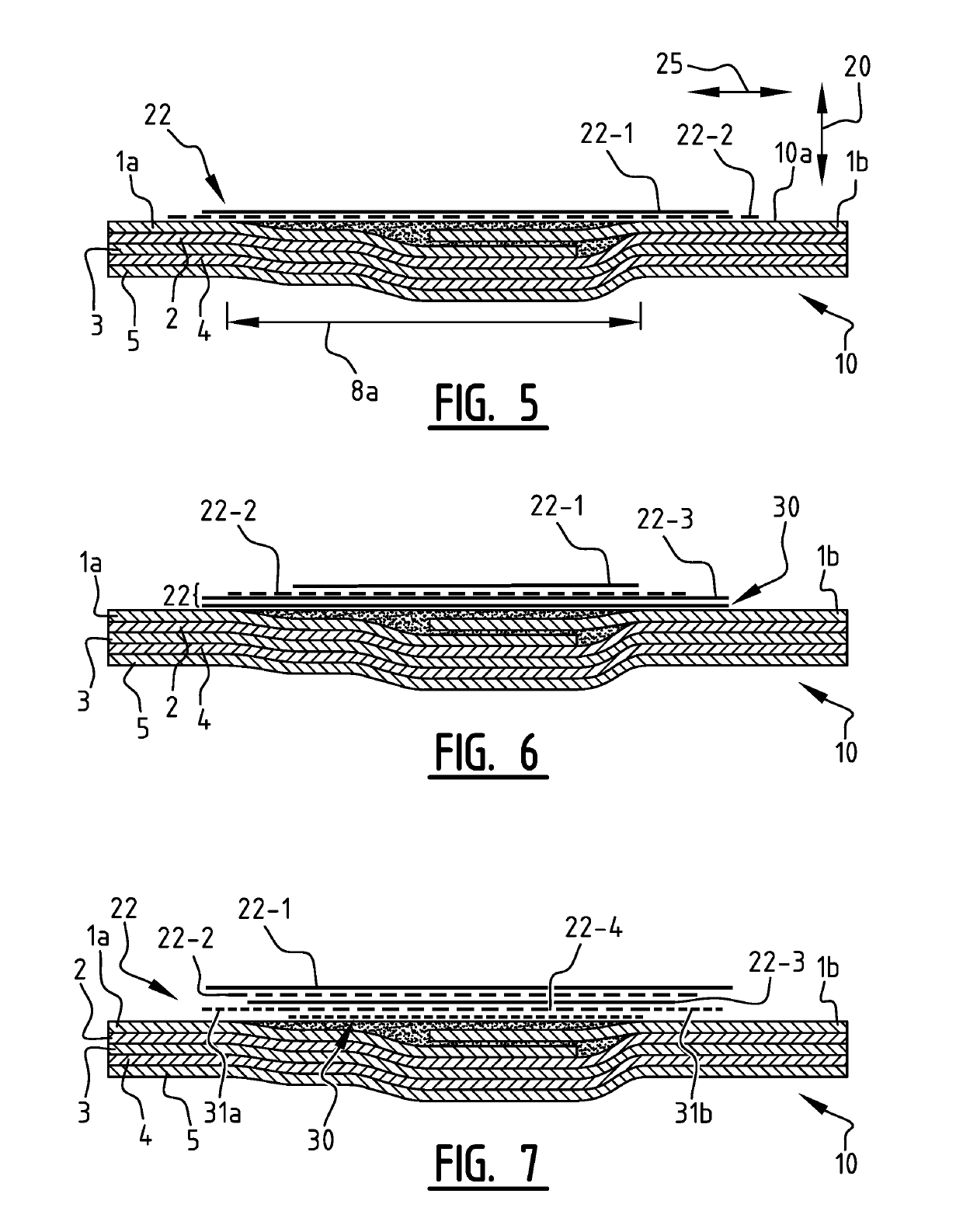
[0091]The strap over the critical location 7 consists of 4 layers. These layers are positioned symmetrically over the critical location 7 with increasing width towards the outside of the structure. The overlap is at each side minimally 5*tlayer i. Therefore:

0.5(b−a)≥5*tlayer 2, 0.5(c−b)≥5*tlayer 3 and 0.5(d−c)≥5*tlayer 4

[0092]Layer 1 and layer 3 are UD CFRP layers with a fibre strength of 4,000 MPa and a fiber volume fraction FVF of 50% and a composite layer with a of thickness tc=0.15 mm and ...


PUM

PropertyMeasurementUnit
Pressureaaaaaaaaaa
Pressureaaaaaaaaaa
Energyaaaaaaaaaa

Abstract

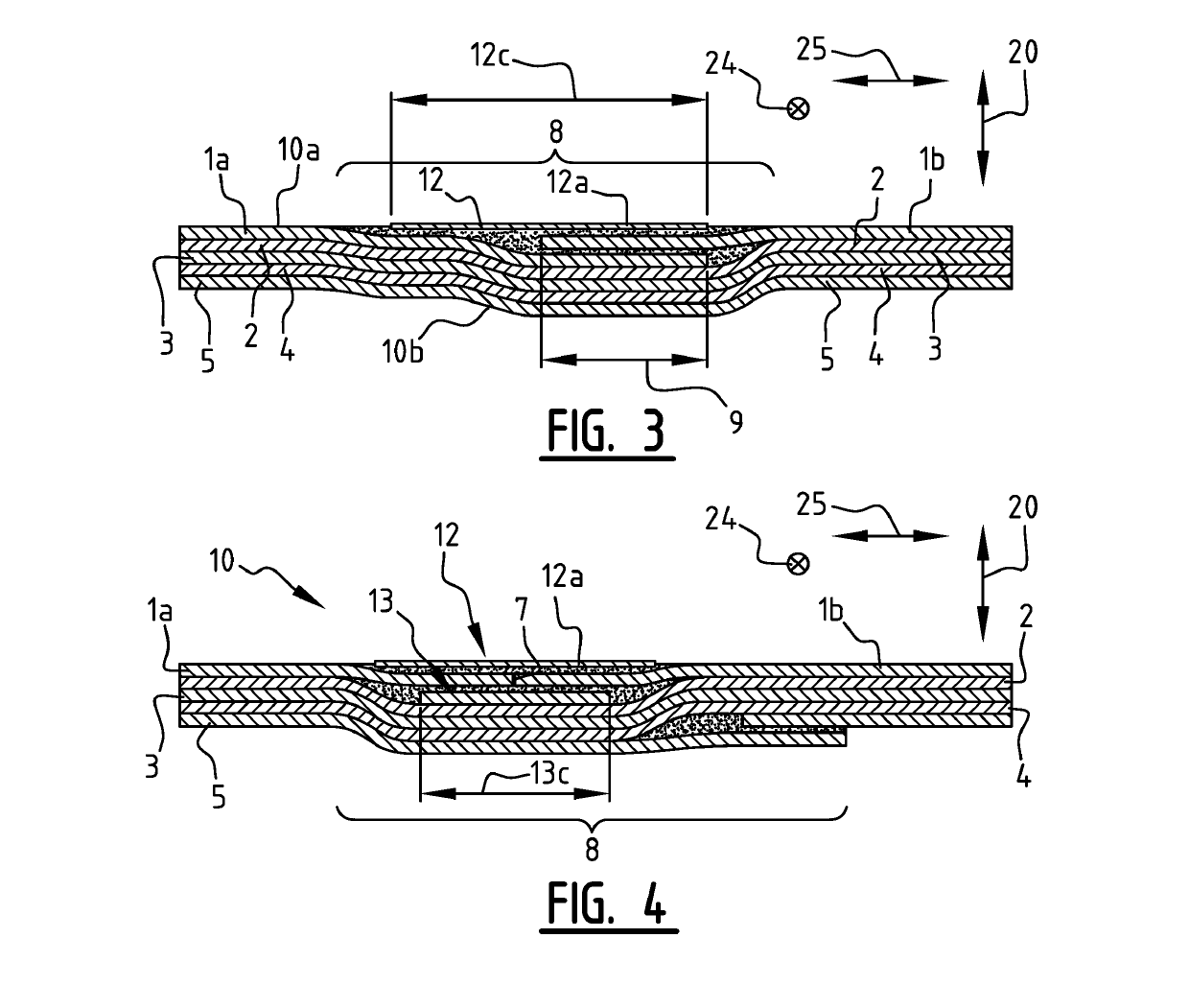
Described is a laminate, including a stack of mutually bonded adhesive layers and metal sheets. The laminate includes abutting and / or overlapping metal sheet edges that extend along a length direction within a splicing region. A splice strap is connected to the laminate at an outer surface of the laminate across said splicing region. The splice strap includes one layer of fiber-reinforced adhesive or of metal sheet, or stacked layers of fiber-reinforced adhesive and / or metal sheets. A widest splice strap layer is connected to the laminate over a transverse distance of at least 5 times the widest strap layer thickness, and the widest strap layer has a lower bending stiffness than the bending stiffness of one of the spliced metal sheets.

Description

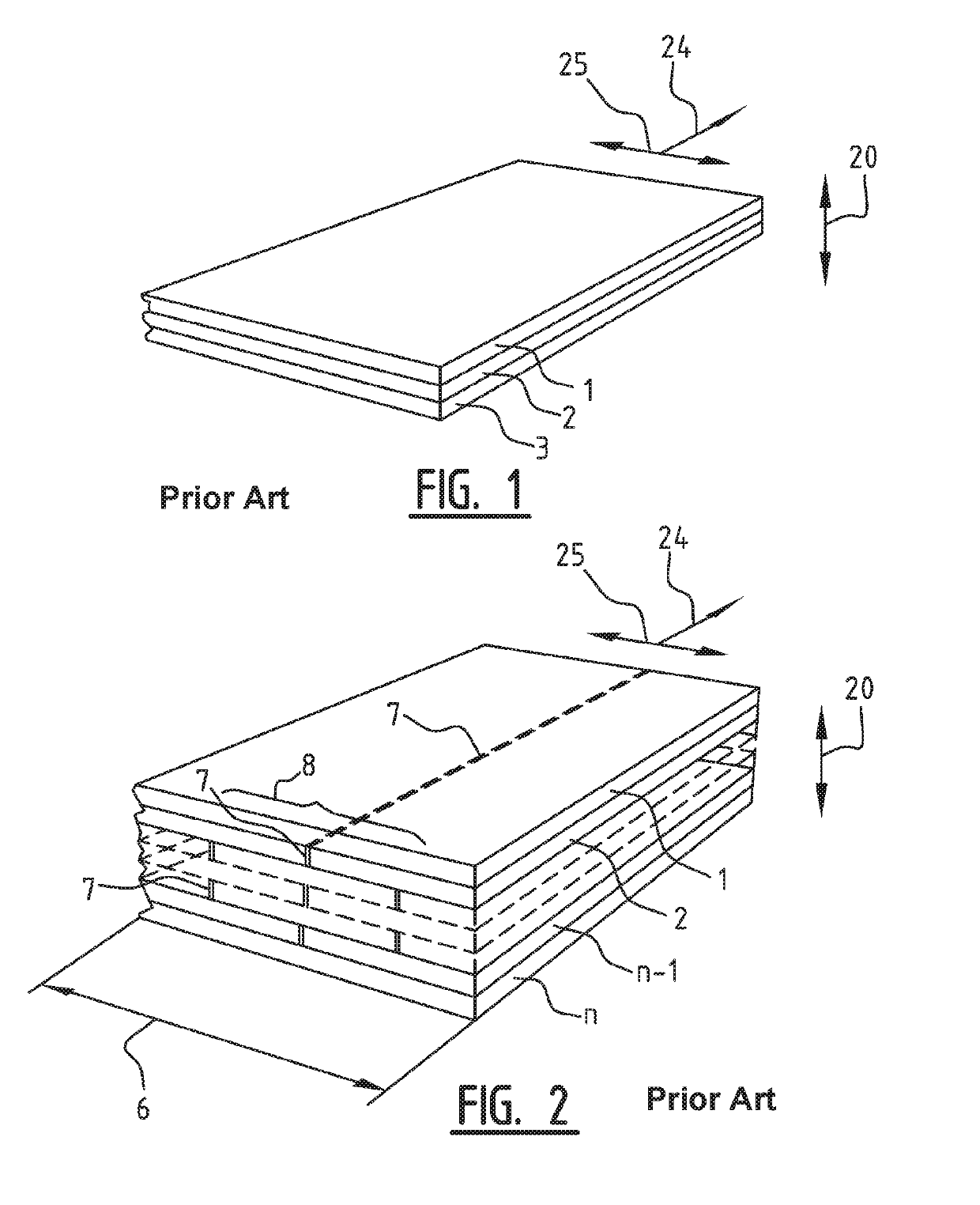
CROSS-REFERENCE TO RELATED APPLICATIONS[0001]This application is the United States national phase of International Application No. PCT / NL2016 / 050636 filed Sep. 15, 2016, and claims priority to Dutch Patent Application No. 2015437 filed Sep. 15, 2015, the disclosures of which are hereby incorporated in their entirety by reference.FIELD OF THE INVENTION[0002]The invention relates to a laminate of mutually bonded adhesive layers and metal sheets with abutting and / or overlapping metal sheet edges, extending along a length direction within a splicing region of the laminate. The invention further relates to a method for obtaining such a laminate.BACKGROUND ART[0003]Laminates of mutually bonded adhesive layers and metal sheets are used for structural purposes, for instance in the aircraft industry. In order to obtain large panels of such laminates, and because metal sheets are available in limited widths only, typical laminates comprise abutting and / or overlapping metal sheet edges, extend...

Claims


Application Information

Patent Timeline
IPC IPC(8): B32B15/08B64C1/12B64G1/22B32B5/12B32B7/14B32B3/08B32B7/04B32B15/14B32B15/20
CPCB32B15/08B32B7/05B64G1/22B32B5/12B32B7/14B32B3/08B32B15/14B32B15/20B64C2001/0072B32B2250/42B32B2250/44B32B2260/021B32B2262/101B32B2307/51B32B2307/54B32B2307/546B32B2307/552B32B2605/18B64C1/12B32B2605/00B32B5/02B32B7/12B32B15/043B32B15/082B32B15/088B32B15/09B32B15/092B32B15/098B32B15/18B32B27/28B32B27/281B32B27/285B32B27/286B32B27/30B32B27/32B32B27/34B32B27/36B32B27/42B32B3/02B32B3/10B32B3/14B32B2260/046B32B2262/0269B32B2262/106B32B2307/50B32B2307/714B32B2307/732Y10T428/192Y10T428/197
Inventor GUNNINK, JAN WILLEMGUNNINK, SIMON
Owner GTM ADVANCED PROD
Learn More