Wire harness

a wire harness and wire technology, applied in the direction of insulated conductors, cables, coupling device connections, etc., can solve the problems of air inside the coating materials being cut off from escaping, and achieve the effect of ensuring waterproof properties

Active Publication Date: 2019-05-02
AUTONETWORKS TECH LTD +2
View PDF9 Cites 3 Cited by
  • Summary
  • Abstract
  • Description
  • Claims
  • Application Information

AI Technical Summary

Benefits of technology

[0011]With the wire harness according to the preferred embodiment, the outer periphery of the region containing the exposed conductor portion and the coating material end portions adjacent to the exposed conductor portion, of the insulated wires is continuously covered with the film-like or tubular protective material, and, at each of the coating material end portions, the gap between the coating material and the protective material covering the coating material is sealed with the waterproofing agent. Thus, the intrusion of water into the exposed conductor portion from the gaps between the protective material and the individual coating materials and from outside the protective material can be suppressed, so that waterproofing properties are ensured. Moreover, at least one insulated wire of the plurality of insulated wires has a flow path through which gas flows, the flow path being created in the gaps between the strands that constitute the conductor and reaching from the coating material end portion opposite to the coating material end portion adjacent to the exposed conductor portion to the splice portion. Thus, air inside the coating material of this insulated wire has an escape route to the exposed conductor portion. Accordingly, even when this insulated wire is exposed to a high temperature, the air inside the coating material flows to the exposed conductor portion, and loosening of a waterproofing rubber stopper due to pressure applied by expanded air moving toward a connecting terminal opposite to the exposed conductor portion can be suppressed.
[0012]At this time, when at least one insulated wire of the plurality of insulated wires is an insulated wire whose conductor partially exposed at an intermediate portion of the wire in its longitudinal direction is joined to the exposed conductor of another insulated wire in the splice portion, and the insulated wire has a flow path through which gas flows, the flow path being created in the gaps between the strands that constitute the conductor of the insulated wire and reaching from one end to the other end of the wire in the longitudinal direction, even when the insulated wire is exposed to a high temperature, air inside the coating material flows to a portion of the insulated wire that is not exposed to the high temperature. Thus, loosening of a waterproofing rubber stopper due to pressure applied by expanded air moving toward a connecting terminal opposite to the exposed conductor portion can be suppressed even more.
[0013]Furthermore, when two or more insulated wires of the plurality of insulated wires each have a flow path through which gas flows, the flow path being created in the gaps between the strands that constitute the conductor and reaching from the coating material end portion opposite to the coating material end portion adjacent to the exposed conductor portion to the splice portion, even when one of these insulated wires is exposed to a high temperature, air inside the coating material of this insulated wire flows to the inside of the coating material of another insulated wire whose flow path is connected to the flow path of the insulated wire exposed to the high temperature. Thus, loosening of a waterproofing rubber stopper due to pressure applied by expanded air moving toward a connecting terminal of this insulated wire that is opposite to the exposed conductor portion can be suppressed even more.

Problems solved by technology

However, as a result of the gaps between the strands that constitute the conductors being filled with the resin material, air inside the coating materials is cut off from escaping to the exposed conductor portion.

Method used


Image

  • Wire harness
  • Wire harness
  • Wire harness

Examples


examples

[0044]Hereinafter, examples and comparative examples will be described.

examples 1 to 5

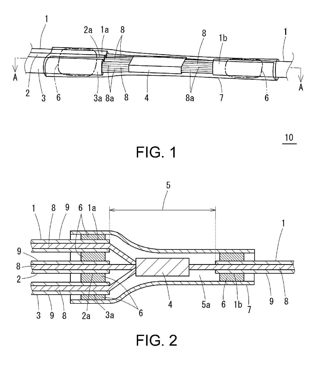
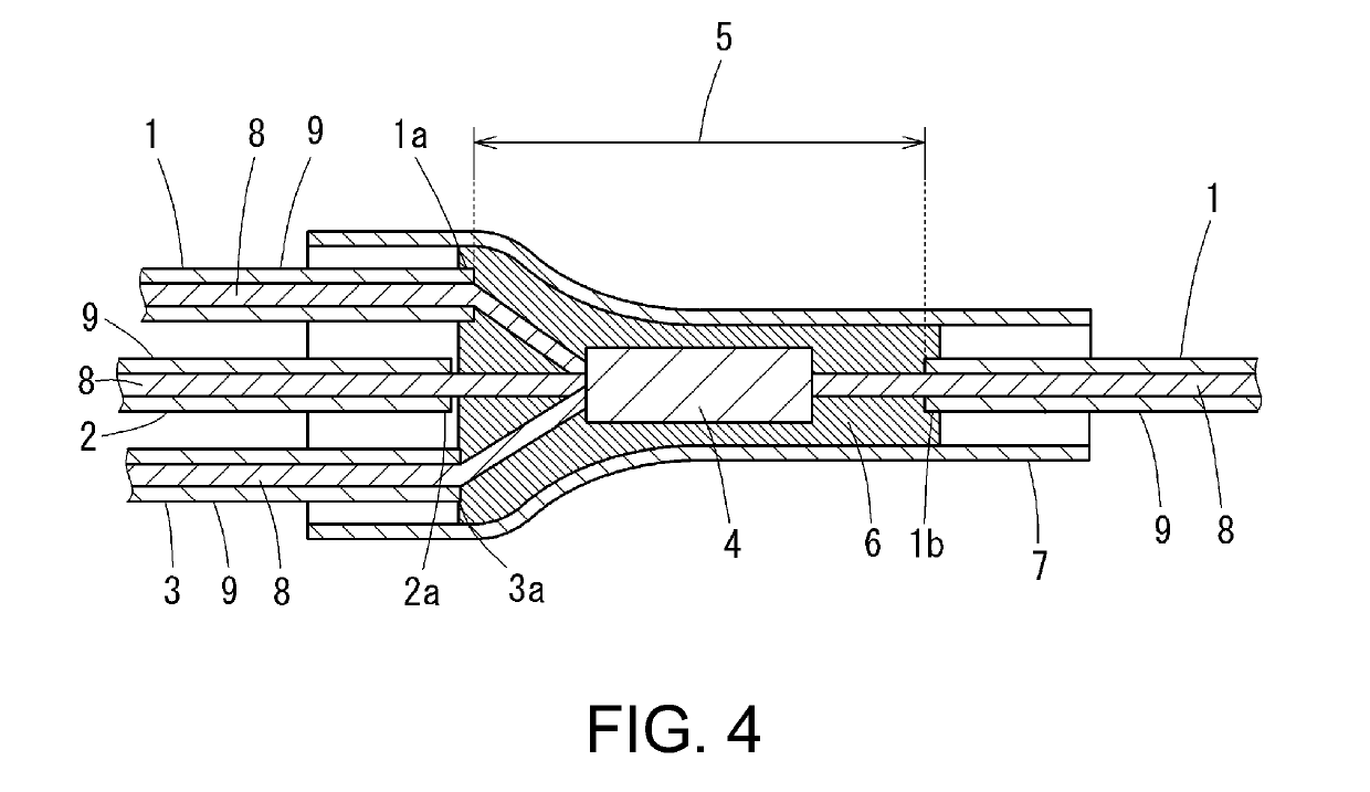
[0045]An insulated wire 1 (outer diameter: 2.1 mm, length: 300 mm) with a coating material formed using a vinyl chloride resin, and insulated wires 2 and 3 (outer diameter: 2.1 mm, length: 150 mm) with a coating material formed using a vinyl chloride resin were prepared. A length of 20 mm of the coating material of the insulated wire 1 at a middle portion of the insulated wire 1 in the longitudinal direction was stripped, and a length of 15 mm of the coating materials of the insulated wires 2 and 3 at an end portion of the respective insulated wires 2 and 3 was stripped. The thus exposed conductors were bundled together, and joined together through ultrasonic welding to form an intermediate splice portion 4 (FIG. 5(a)). The wire bundle was placed on a transparent protective film 7 (70 mm×70 mm×10 μm) made of PVC such that the exposed conductor portion 5 including the intermediate splice portion 4 was at the center of the protective film 7 (FIG. 5(a)). Then, 0.3 g of a waterproofing ...

example 6

[0049]A wire harness was produced in the same manner as in Example 1 except that a film without pressure-sensitive adhesive properties (“Saran Wrap” (registered trademark) manufactured by Asahi Kasei Corporation) was used as the protective film 7, and a piece of pressure-sensitive adhesive tape made of PVC was wrapped around that film.


PUM

PropertyMeasurementUnit
viscosityaaaaaaaaaa
viscosityaaaaaaaaaa
temperatureaaaaaaaaaa

Abstract

A wire harness can ensure waterproofness of an exposed conductor portion, and even when at least one of insulated wires is exposed to a high temperature, can suppress loosening of a rubber stopper of a waterproofing terminal. An outer periphery of a region containing an exposed conductor portion and coating material end portions is continuously covered with a protective film. At each of the coating material end portions, a gap between a coating material and the protective film covering the coating material is sealed with a waterproofing agent. At least one insulated wire has a flow path through which gas flows, the flow path being created in gaps between strands that constitute a conductor of the insulated wire and reaching from a coating material end portion opposite to the coating material end portion adjacent to the exposed conductor portion to a splice portion.

Description

TECHNICAL FIELD[0001]The present disclosure relates to a wire harness, and more particularly relates to a wire harness in which an exposed conductor portion including a splice portion of insulated wires is waterproofed.BACKGROUND ART[0002]In an in-vehicle wire harness, for example, there are cases where conductors of insulated wires are partially exposed at intermediate portions or the like of the insulated wires, and the exposed conductors are joined together to form a splice portion. An exposed conductor portion including the thus formed splice portion is covered and protected with a resin material.CITATION LISTPatent Documents[0003]Patent Document 1: Japanese Patent No. 5418457SUMMARYTechnical Problem[0004]When the exposed conductor portion formed of a bundle of exposed conductors including the splice portion is covered with a resin material, the resin material penetrates into gaps between strands constituting these conductors. When the resin material completely penetrates into t...

Claims


Application Information

Patent Timeline
Patent Type & Authority Applications(United States)
IPC IPC(8): H01B7/282H01B7/00H01R4/72H02G15/24
CPCH01B7/2825H01B7/0045H01R4/72H02G15/24H01R4/029H01R4/18Y02A30/14H02G15/18H01B7/285H01R13/5205H01R13/5216
Inventor ITOU, KENJITAKADA, TAKASHI
Owner AUTONETWORKS TECH LTD
Why Eureka
Try Eureka