Terminal fitting

a technology of fittings and fittings, applied in the direction of contact member manufacturing, dustproof/splashproof/drip-proof/waterproof/flameproof connections, coupling device connections, etc., can solve the problems of inability to reliably avoid water contact with the core, possible displacement of waterproof walls, etc., to achieve excellent formability, ensure waterproof properties, and ensure the effect of waterproof properties

Inactive Publication Date: 2015-03-31
AUTONETWORKS TECH LTD +2
View PDF6 Cites 2 Cited by
  • Summary
  • Abstract
  • Description
  • Claims
  • Application Information

AI Technical Summary

Benefits of technology

[0011]Since the tube is held in close contact with the barrel portion and the waterproof wall while surrounding the core, the contact of water with the core can be prevented and waterproof property can be ensured. Further, since the movement of the waterproof wall toward the main portion is restricted by the contact of the restricting portion with the waterproof wall from the main portion side, the tube can be reliably held in close contact with the waterproof wall and high waterproof property can be maintained.
[0012]Since the restricting portion is formed by being bent from the coupling portion located between the main portion and the barrel portion, formability is excellent without particularly complicating the structure of the restricting portion.
[0013]Since the restricting portion includes the second restricting portion that comes into contact with the waterproof wall from the barrel portion side in addition to the first restricting portion, a movement of the waterproof wall toward the barrel portion can also be restricted and reliability in movement restriction can be improved. Further, even if the waterproof wall is thinned to such an extent that it is difficult to stand alone, it can be supported by the first and second restricting portions. The waterproof wall can be thinned and the entire length of the terminal fitting can be correspondingly made shorter.
[0014]Since the space into which the waterproof wall is to be positioned and inserted is formed between the first and second restricting portions, a displacement of the waterproof wall can be prevented and the tube can be reliably held in close contact with the waterproof wall at a predetermined position.

Problems solved by technology

However, in this case, the waterproof wall may possibly be displaced in a direction away from the wire barrel portion.
Then, there is a problem that the leading end of the heat shrinkable tube does not reach the waterproof wall and the contact of water with the core cannot be reliably avoided.

Method used


Image

  • Terminal fitting
  • Terminal fitting
  • Terminal fitting

Examples


first embodiment

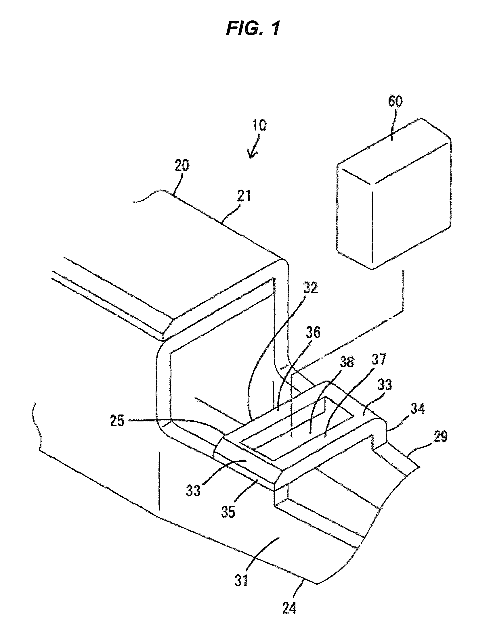
[0024]the present invention is described with reference to FIGS. 1 to 3. A terminal fitting 10 according to the first embodiment includes a terminal main body 20, a waterproof wall 60 and a heat shrinkable tube 70 and is connected to an end portion of a wire 90 as shown in FIG. 2.

[0025]The terminal main body 20 is integrally formed, such as by bending a metal plate made of copper or copper alloy and composed of a main portion 21, barrel portions 22, 23 located behind the main portion 21, a coupling portion 24 located between the barrel portions 22, 23 and the main portion 21 to couple them, and a restricting portion 25 formed integrally to the coupling portion 24.

[0026]The main portion 21 is formed into a substantially rectangular tubular shape with open front and rear surfaces by bending the metal plate in a width direction a plurality of times. A resilient contact piece 26 is formed in the main portion 21. The resilient contact piece 26 is in the form of a cantilever folded backwa...

second embodiment

[0050] the spacing of the space 38A of the restricting portion 25A needs not coincide with the thickness of the waterproof wall 60 in forward and backward directions and strict gap management is not necessary since the waterproof wall 60 is resiliently held in the restricting portion 25A.

third embodiment

[0051]FIGS. 7 and 8 show the present invention. A terminal fitting 10B according to the third embodiment also differs from the first embodiment in the structure of a restricting portion 25B.

[0052]The restricting portion 25B is integrally coupled to both side plate portions 29, 31 of a coupling portion 24. Specifically, as shown in FIG. 8, the restricting portion 25B is composed of a pair of projecting pieces 51 bent inwardly substantially at a right angle from the upper ends of the both side plate portions 29, 31. The both projecting pieces 51 are in the form of rectangular plates and substantially horizontally arranged substantially at the same height position. The projecting ends of the both projecting pieces 51 are spaced apart by a distance shorter than the width of a waterproof wall 60B. Further, the rear ends of the both projecting pieces 51 and the front end of a core 91 are spaced apart by a distance longer than the thickness of the waterproof wall 60B in forward and backwar...


PUM


Abstract

An object of the present invention is to provide a terminal fitting with improved waterproof property. A terminal fitting (10) includes a box-shaped main portion (21), barrel portions (22, 23) to be crimped and connected to a core (91) at an end portion of a wire (90), a waterproof wall (60) to be mounted between the barrel portions (22, 23) and the main portion (21) to partition between them in a liquid-tight manner, a restricting portion (25) configured to restrict a movement of the waterproof wall (60) toward the main portion (21) by coming into contact with the waterproof wall (60) from the main portion (21) side and a heat shrinkable tube (70) to be held in close contact with the barrel portions (22, 23) and the waterproof wall (60) while surrounding the core (91).

Description

BACKGROUND OF THE INVENTION[0001]1. Field of the Invention[0002]The present invention relates to a terminal fitting.[0003]2. Description of the Related Art[0004]A conventional terminal fitting is disclosed in Japanese Unexamined Patent Publication No. 2000-285983. This includes a main portion connectable to a mating terminal fitting, a wire barrel portion to be crimped and connected to a core at an end portion of a wire, an insulation barrel portion to be crimped and connected to an insulation coating at the end portion of the wire and a coupling portion located between the wire barrel portion and the main portion. Further, a heat shrinkable tube is mounted on a part from the insulation barrel portion to the coupling portion. A connecting part between the terminal fitting and the wire is made waterproof by this heat shrinkable tube.[0005]In the case of the conventional terminal fitting, the leading end of the heat shrinkable tube is open. Thus, water may enter through the leading en...

Claims


Application Information

Patent Timeline
Patent Type & Authority Patents(United States)
IPC IPC(8): H01R13/52H01R4/18H01R4/20H01R4/72H01R13/04H01R13/11H01R43/00H01R43/16
CPCH01R13/52H01R4/184H01R4/20H01R4/72H01R13/04H01R13/113H01R43/005H01R43/16
Inventor UCHIYAMA, YOSHIHIROMORIKAWA, SATOSHIOOTSUKA, TAKUJISASAKI, CHIKAMASAHIRAI, HIROKIONO, JUNICHI
Owner AUTONETWORKS TECH LTD
Why Eureka
Try Eureka