Assembly and Method for Plugging and Unplugging a Port

a technology of stoppers and plugs, applied in the direction of mechanical equipment, pipes/joints/fittings, pipe elements, etc., can solve the problems of inconvenient finger grip, unfavorable operation, and inability to use, etc., to achieve convenient finger grip

Inactive Publication Date: 2019-05-02
NG YEOW
View PDF13 Cites 0 Cited by
  • Summary
  • Abstract
  • Description
  • Claims
  • Application Information

AI Technical Summary

Benefits of technology

[0010]With the inventive stopper held by such pliers, the operator may forwardly extend both the pliers and the stopper toward a port to be plugged. During such forward extension, the stopper and plier jaws conveniently pass the port's periphery situated obstructions without interference. Thereafter, the operator may further forwardly drive the stopper into the port and may simultaneously axially turn or twist the stopper via manually applied torque to the pliers.
[0011]The above described pliers actuated stopper insertion steps may be most advantageously performed in circumstances where structures and protrusions at and about the port prevent utilization of other tools such as wrenches, or prevent the operator's direct use of his or her hand and fingers for application of the needed turning force to the stopper.
[0012]A reversal of steps described above effectively allows the provided pliers to lend assistance in the stopper's extraction.
[0013]In a preferred embodiment, the inventive stopper incorporates a plurality of torsion lands which are formed or molded at the periphery of the stopper's base. Also, in the preferred embodiment, the torsion lands configure the base as a square having four orthogonal faces. In situations where the stopper is to be utilized for plugging and unplugging a port which is removed from any adjacent obstructions or protuberances, the jaws of a wrench engaged with opposing lands of such orthogonal base, and the wrench may be utilized as an alternative means for application of the needed turning force. Such square configuration of the base also provides convenient finger grip surfaces which allow direct hand actuated turning of the stopper.

Problems solved by technology

However, the structures and protrusions adjacent the port may undesirably mechanically interfere with and prevent an operator's utilization of a hand or a wrench to apply the needed turning force to the stopper during insertion.
Peripheral protrusions and obstructions at and around a stoppered port may similarly interfere with application of a turning force for assistance in the extraction of the stopper.

Method used


Image

  • Assembly and Method for Plugging and Unplugging a Port
  • Assembly and Method for Plugging and Unplugging a Port
  • Assembly and Method for Plugging and Unplugging a Port

Examples


Embodiment Construction

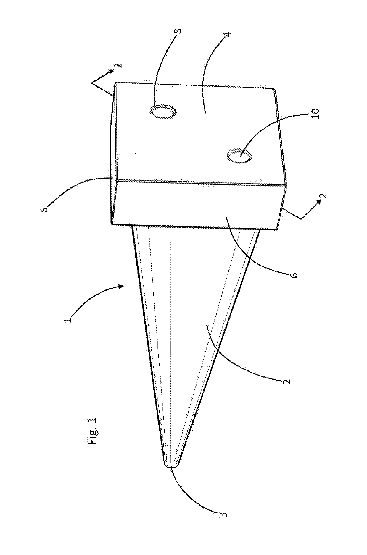
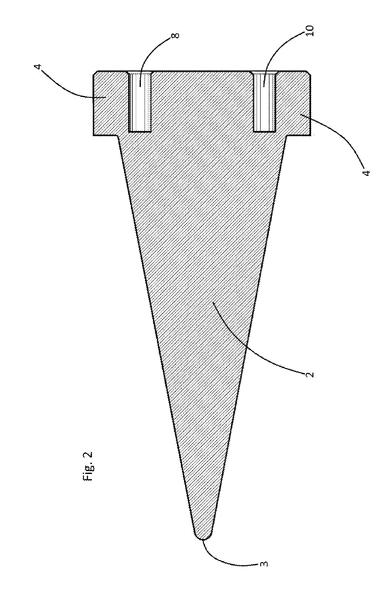
[0021]Referring now to the drawings, and in particular to Drawing FIG. 1, a preferred embodiment of the instant inventive stopper assembly is referred to generally by Reference Arrow 1. The stopper assembly 1 includes a conical body 2 having a forward insertion end 3. A base 4 is fixedly attached to or formed wholly with the rearward end of the conical body 2, the base 4 having at least a pair of forwardly extending and rearwardly opening sockets 8 and 10. In a preferred embodiment, the base 4 incorporates a plurality of torsion lands 6 about its periphery, such lands 6 suitably being orthogonally arranged with respect to each other to form a substantially square base or stopper head. In the preferred embodiment, the base 4 and the conical body 2 are integrally formed of an elastomer such as molded nitrile butadiene rubber (NBR) or silicone rubber.

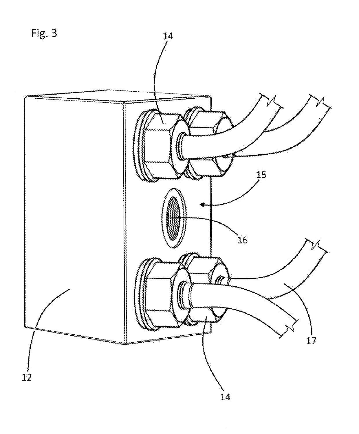
[0022]Referring to FIG. 5, a simple and unobstructed use environment for the inventive stopper 1 may comprise a terminal end 28 of a hydr...


PUM


Abstract

A stopper assembly incorporating an elastic conical body having a forward end and a rearward end; a base attached to the conical body's rearward end; and a pair of sockets opening at the base; and a method for using the stopper assembly including steps of providing the stopper assembly and needle nose pliers; grasping the pliers' handles and splaying pliers' jaws; inserting the nose of each such jaw into one of the sockets; squeezing the pliers' handles for clamping the pair of sockets between the pliers' jaws; moving the pliers, the base, and the elastic conical body toward and into the port; and simultaneously driving and twisting the pliers and the stopper assembly.

Description

FIELD OF THE INVENTION[0001]This invention relates to stoppers and plugs for closing ports and openings. More particularly, this invention relates to stoppers having specialized adaptations for assisting in stopper insertions and stopper extractions.BACKGROUND OF THE INVENTION[0002]Rubber opening or port closing stoppers are commonly inserted into and extracted from ports which are relatively inaccessible or which include peripheral or surrounding obstructions. During insertion of a rubber stopper into such a port, it is commonly desirable to simultaneously forwardly drive the stopper and to simultaneously circumferentially twist or turn the stopper about its longitudinal axis. Such simultaneous driving and turning action applied to a stopper during insertion assists in maintaining or prolonging relatively low sliding friction at the annular interface between the stopper's conical wall and the port's wall, such increase in the duration of sliding friction advantageously allowing the...

Claims


Application Information

Patent Timeline
Patent Type & Authority Applications(United States)
IPC IPC(8): F16L55/11
CPCF16L55/1141
Inventor NG, YEOW
Owner NG YEOW
Why Eureka
Try Eureka