Electrical Installation For An Electric Trace Heating System For A Metal Pipe For Transporting Fluids And Electric Trace Heating Method For Such A Pipe

a technology of electric trace heating system and metal pipe, which is applied in the direction of pipe heating/cooling, fault location by conductor type, mechanical equipment, etc., can solve the problems of affecting the operation in particular methane, being contained, and the question is scrapped entirely. , to achieve the effect of redundancy of the three-phase electric circuit and reducing the risk of gas molecules

Active Publication Date: 2019-05-02
SAIPEM SA
View PDF0 Cites 5 Cited by
  • Summary
  • Abstract
  • Description
  • Claims
  • Application Information

AI Technical Summary

Benefits of technology

The invention proposes an electrical installation that provides redundancy of three-phase electric circuits while limiting the number of electric cables needed. When failure occurs in a circuit, only the failed cable needs to be replaced instead of scrapping the whole circuit. This is possible because the main and additional cables are connected together at the pipeline end to the same zero electric potential. The invention allows for -100% redundancy with a single additional cable, compared to the prior art that requires a complete additional circuit for -300% redundancy. The redundant circuit is balanced, which makes it easier to detect any failure by monitoring the current flow in the additional cable.

Problems solved by technology

Unfortunately, if no provision is made for conserving some minimum threshold temperature inside such pipes, there is a major risk of molecules of gas, in particular of methane, that are contained in the fluids being transported combining at low temperature with molecules of water so as to form hydrate crystals.
Likewise, the oil solubility of high molecular weight compounds, such as paraffins or asphaltenes, decreases with lowering temperature, thereby giving rise to solid deposits that can also block flow.
However, even though the failure of a three-phase circuit is generally due to the failure of only one of its electric cables, the circuit in question is scrapped entirely, including its electric cables that have not failed.

Method used


Image

  • Electrical Installation For An Electric Trace Heating System For A Metal Pipe For Transporting Fluids And Electric Trace Heating Method For Such A Pipe
  • Electrical Installation For An Electric Trace Heating System For A Metal Pipe For Transporting Fluids And Electric Trace Heating Method For Such A Pipe
  • Electrical Installation For An Electric Trace Heating System For A Metal Pipe For Transporting Fluids And Electric Trace Heating Method For Such A Pipe

Examples


Embodiment Construction

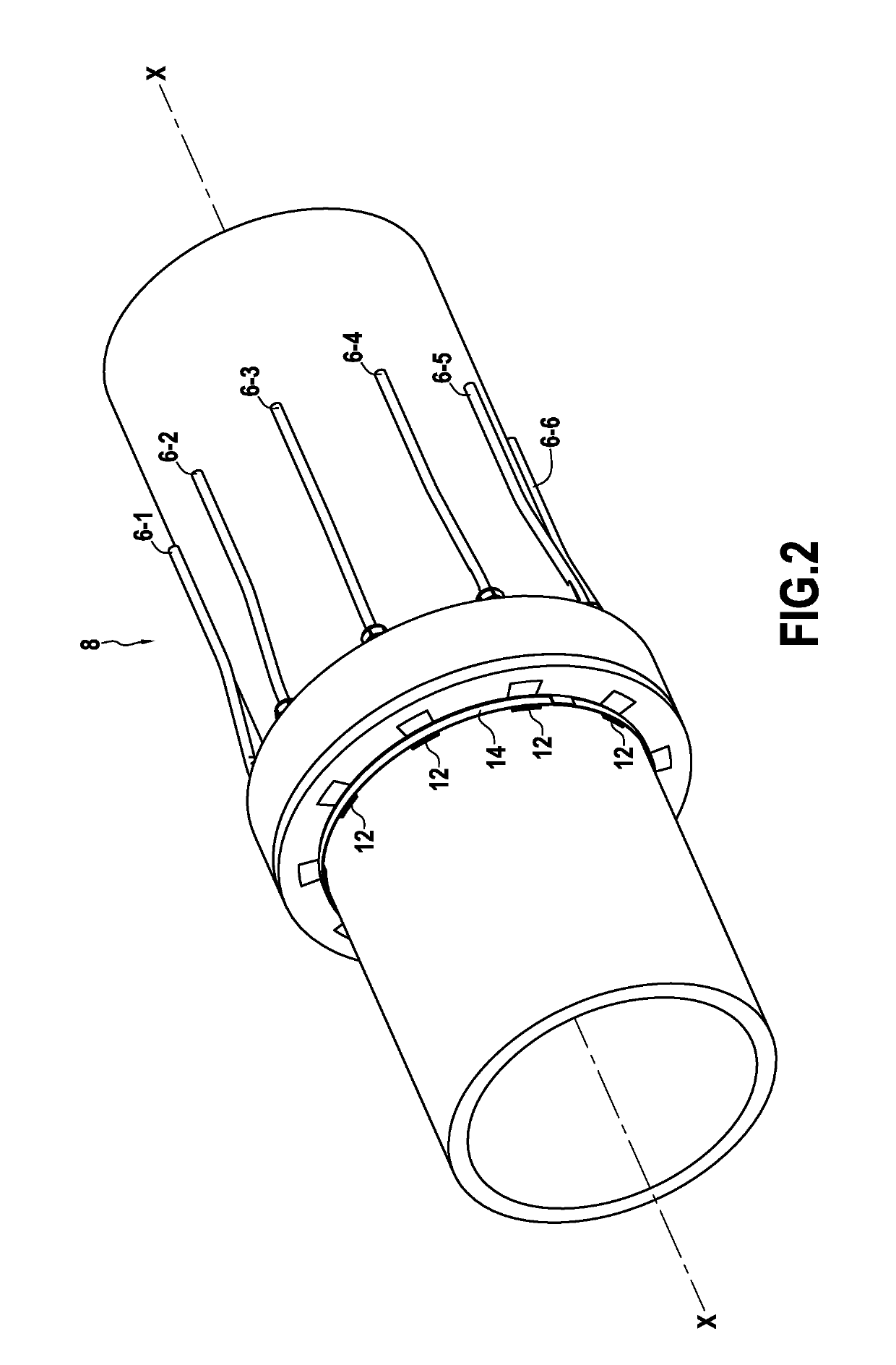
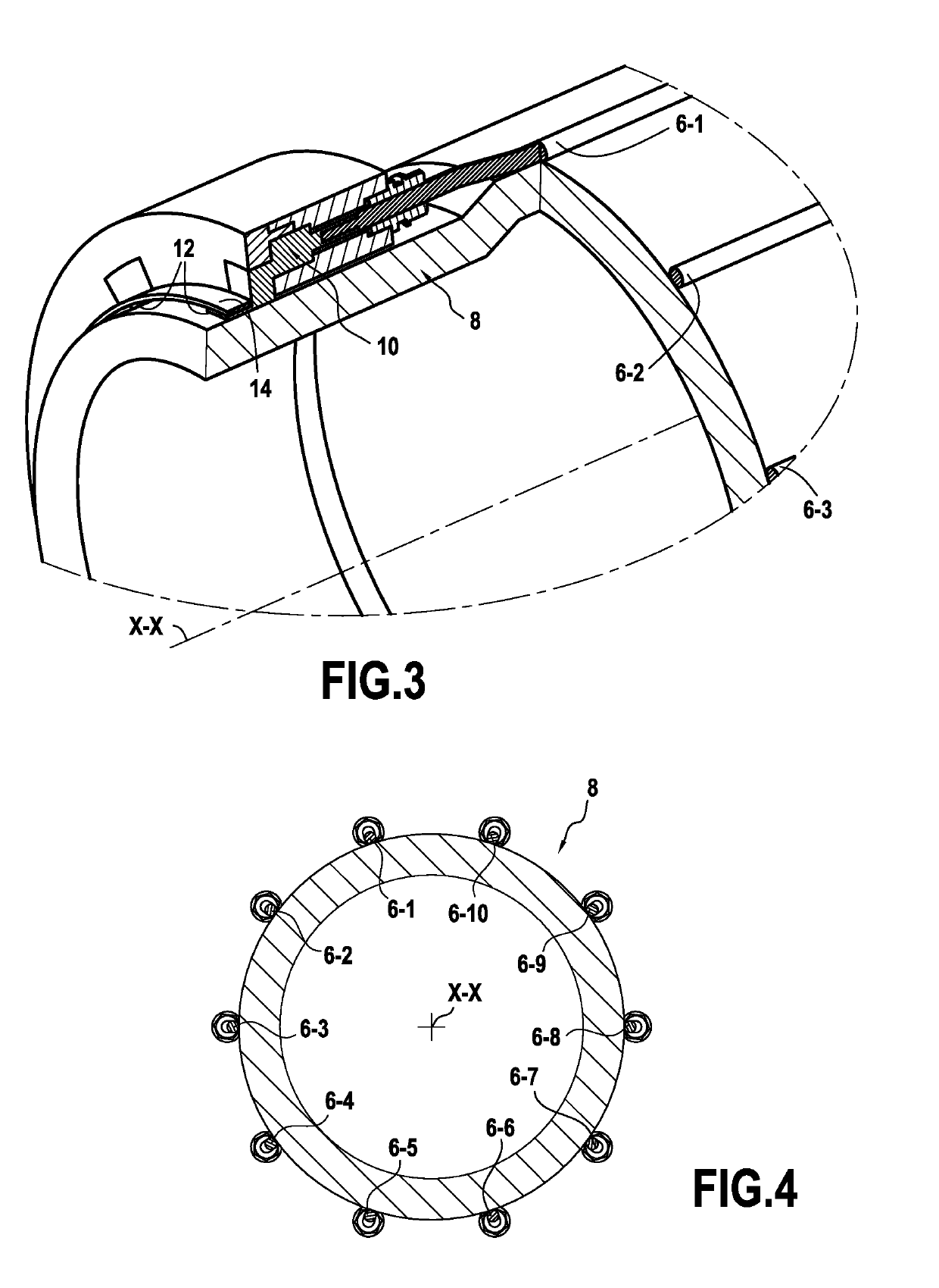
[0031]The invention applies to trace-heating any undersea or on-land metal pipe for transporting fluids, and in particular for electrically trace-heating steel undersea pipes resting on the sea bottom and providing transport between undersea wells producing hydrocarbons, in particular oil and gas, and a surface installation.

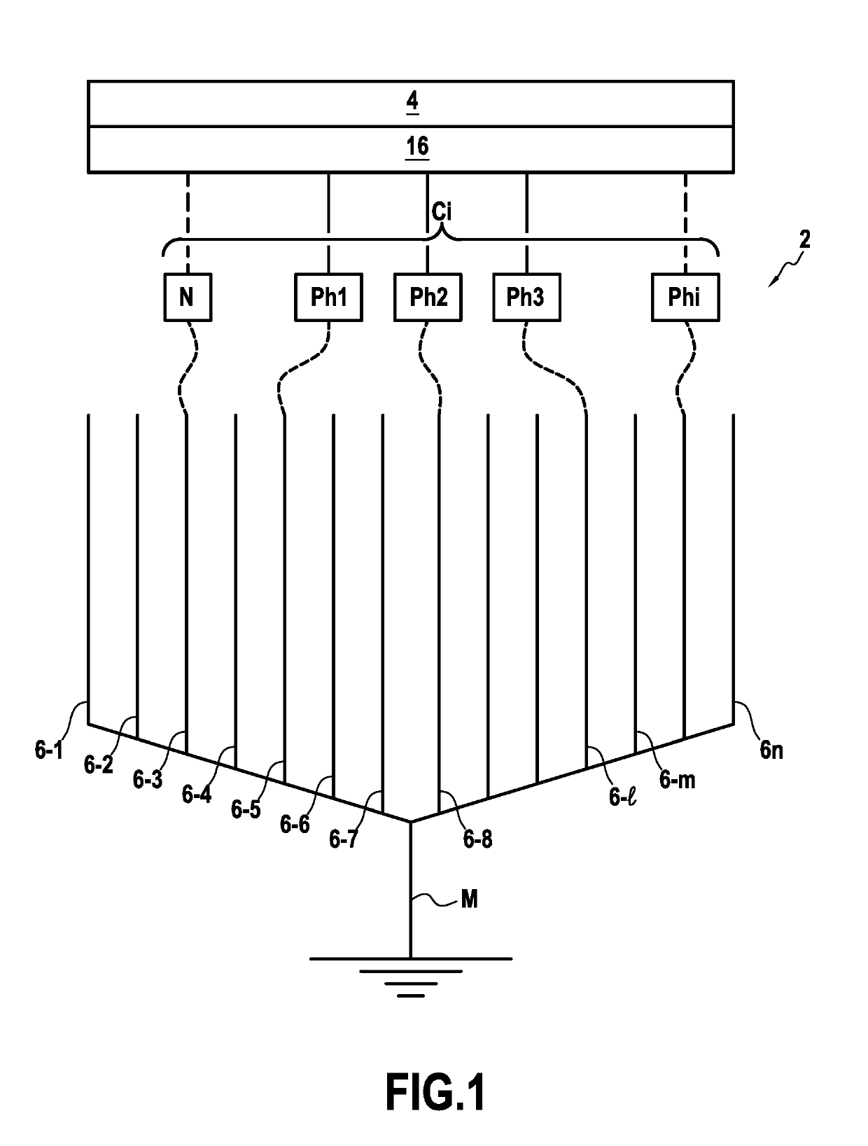
[0032]Heat-tracing a fluid transport metal pipe consists in using an electrical installation of the kind shown in a highly diagrammatic manner in FIG. 1, the electrical installation 2 comprising one or more polyphase electric circuits Cj that are electrically powered from one or more electricity generators 4.

[0033]According to the invention, the electrical installation of the electrical system for trace heating the pipe comprises, for each polyphase electric circuit Cj, n electric cables 6-1, 6-2, . . . , 6-n, where n is an integer greater than or equal to p+1, with p corresponding to the number of phases of the circuit Cj (p being not less than 3). These n elect...


PUM


Abstract

An electrical installation for an electrical system for trace heating a fluid transport pipe (8) made of metal, at least one polyphase circuit having three main electric cables (6-1, 6-4, and 6-7) in a star connection, and one additional electric cable (6-2, 6-3, 6-5, 6-6, 6-8, and 6-9), the main cables and the additional cable positioned around the pipe and connected at the pipeline end to a common connection ring (10) forming a point of zero electric potential, and detector for detecting a failure, if any, of the polyphase circuit to identify a failed main cable in order to replace it with the additional cable.

Description

BACKGROUND OF THE INVENTION[0001]The present invention relates to the general field of electrically trace-heating metal pipes for transporting fluids, and it relates in particular to undersea pipes resting on the sea bottom and providing a connection from undersea wells for producing hydrocarbons, in particular oil and gas, to a surface installation for storage and offloading, e.g. a floating production unit.[0002]In a single offshore hydrocarbon production field, it is common to operate a plurality of wells that may be spaced apart from one another by several kilometers, or even tens of kilometers. The fluids coming from those various wells need to be collected by undersea pipes made of metal (typically steel) laid on the sea bottom, and then transferred by bottom-to-surface connection pipes (“risers”) to a surface installation, e.g. a vessel or a collection point on land, that serves to collect the fluids in order to store them (and optionally process them).[0003]The fluids coming...

Claims


Application Information

Patent Timeline
Patent Type & Authority Applications(United States)
IPC IPC(8): F16L53/38H05B3/56H05B1/02G01R31/08
CPCF16L53/38H05B3/56H05B1/0244G01R31/083H05B2203/021H05B2214/03F17D1/18
Inventor PIONETTI, FRANCOIS-REGISAGOUMI, JALILSUNDERMANN, AXEL
Owner SAIPEM SA
Why Eureka
Try Eureka