Turbomachine

a technology of flow connecting assembly and turbomachine, which is applied in the direction of machines/engines, stators, light and heating apparatus, etc., can solve the problems of negative affecting the flow of the second, and achieve the effect of improving impingement cooling, effective impingement cooling, and effective cooling

Active Publication Date: 2019-05-02
MAN ENERGY SOLUTIONS SE
View PDF28 Cites 2 Cited by
  • Summary
  • Abstract
  • Description
  • Claims
  • Application Information

AI Technical Summary

Benefits of technology

The patent is about improving cooling in a turbomachine assembly by using impingement cooling. The conducting elements in the second medium ensure that the flow of the second medium is directed onto the assembly to be cooled in a defined manner. A gap is formed between the assembly and the impingement grille, and the flow-conducting elements for the second medium extend into the gap by as far as maximally 70% and preferentially minimally 50% of its width, to ensure effective cooling. The flow-conducting elements can be formed as nozzles to increase the flow velocity of the second medium and make the cooling even more effective. Overall, the patent aims to enhance the cooling performance of the turbomachine assembly.

Problems solved by technology

This discharge flow of the second medium out of the gap can negatively affect the flow of the second medium extending through the openings of the impingement grille, which is intended to strike the assembly to be cooled in the region of the second side of the assembly to be cooled.
This is a disadvantage.

Method used


Image

  • Turbomachine
  • Turbomachine

Examples


Embodiment Construction

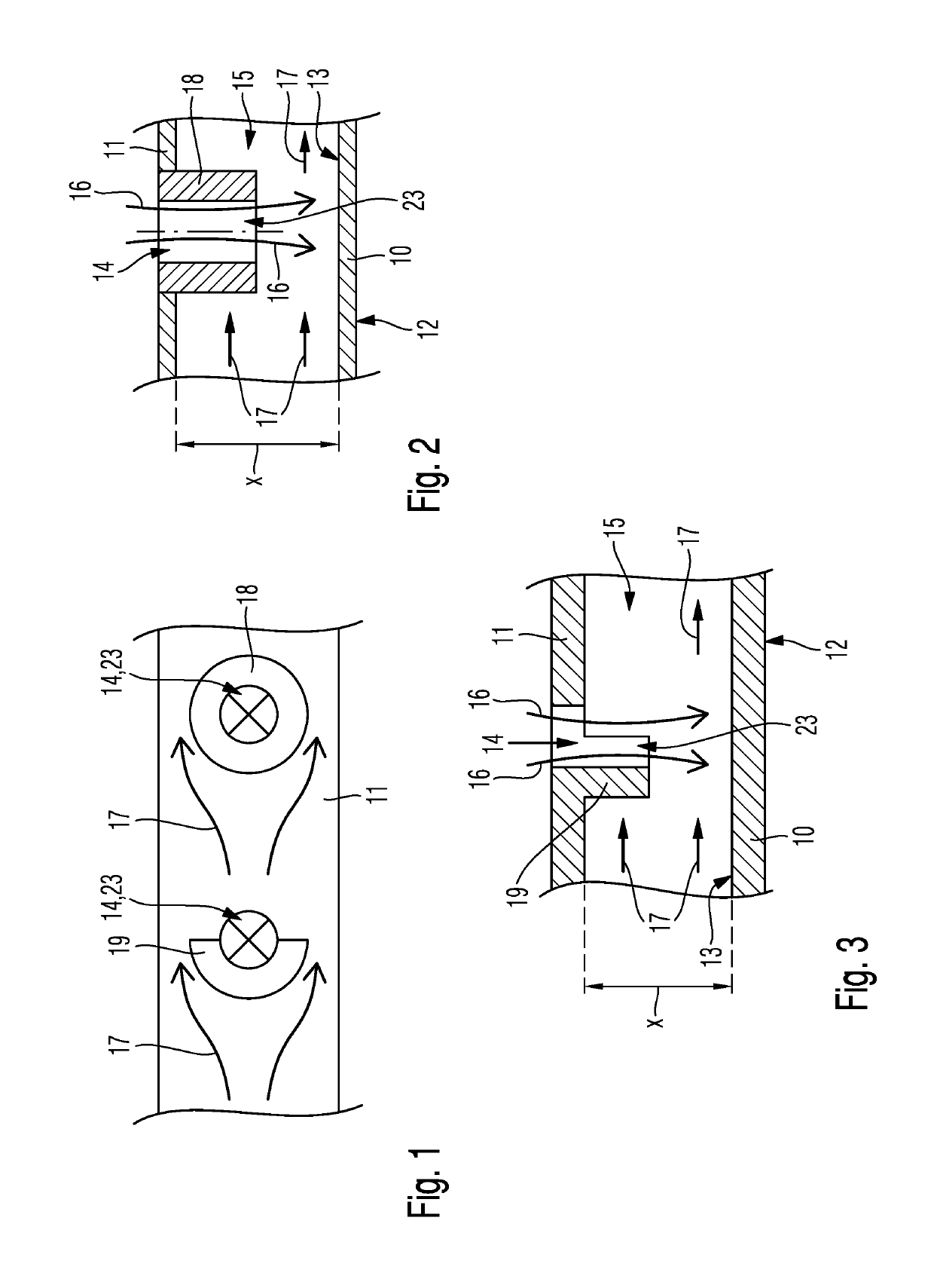
[0019]The present invention relates to a turbomachine, such as for example a turbine, a compressor or a gas turbine, which besides a combustion chamber comprises a turbine. A turbomachine comprises multiple flow-conducting assemblies.

[0020]In a gas turbine, the combustion chamber for example is a flow-conducting assembly which conducts a fuel flow on a first side of a wall of the combustion chamber. Further flow-conducting assemblies of a turbomachine, such as for example a gas turbine, can be so-called cover segments, which radially outside follow moving blades of a turbine stage, for example of a high-pressure turbine stage and on a first side serve for the flow conduction of the medium to be expanded in the turbine.

[0021]Flow-conducting assemblies of a turbomachine are exposed to high temperatures in particular when the first medium to be conducted on the first side of the flow-conducting assembly has a high temperature as is the case in the region of a combustion chamber of a ga...


PUM


Abstract

A turbomachine, with a flow-conducting assembly, which on a first side serves for the flow-conduction of a first medium, which has a first temperature, and which on a second side is coolable with a second medium, which has a second temperature, that is lower than the first temperature, and with an impingement grille including openings which extend spaced from the flow-conducting assembly, wherein via the openings of the impingement grille the second medium is directable onto the second side of the flow-conducting assembly. In the region of at least some of the openings of the impingement grille, flow-conducting elements for the second medium are formed, which emanating from the impingement grille extend in the direction of the second side of the flow-conducting assembly to be cooled.

Description

FIELD OF THE INVENTION[0001]The present invention relates to the cooling of a flow-connecting assembly of a turbomachine.BACKGROUND OF THE INVENTION[0002]Turbomachines, such as for example gas turbines, turbines or compressors, comprise flow-conducting assemblies which on a first side serve for the flow conduction of a first medium, which has a first temperature.[0003]In particular in the case of turbines and in the case of gas turbines in the region of a turbine or of a combustion chamber of the gas turbine, the first medium, which is conducted on the first side of the flow-conducting assembly, has a very high temperature that makes it necessary to cool the flow-conducting assembly. Here it is already known from the prior art to cool the flow-conducting assembly on a second side using a second medium, which has a temperature that is lower than the first temperature.[0004]Accordingly, US2010 / 0126174 discloses a gas turbine with a combustion chamber, wherein a wall of the combustion ...

Claims


Application Information

Patent Timeline
IPC IPC(8): F01D25/12F23R3/00F01D9/06
CPCF01D25/12F23R3/002F01D9/065F23R2900/03044F05D2260/201F05D2250/141F01D5/187F01D9/04F23R3/045F23R3/06
Inventor KREWINKEL, ROBERT
Owner MAN ENERGY SOLUTIONS SE
Why Eureka
Try Eureka