Wide-flow-path highly-efficient gas-liquid separator controlled by utilizing buoy

A technology of gas-liquid separator and buoy, which is applied in separation methods, dispersed particle separation, chemical instruments and methods, etc., can solve problems such as hysteresis, high pressure, and narrow oil well holes, and reduce the impact height and strength, and weaken the shaft The impact and the effect of improving the separation efficiency

Inactive Publication Date: 2020-03-24
HARBIN ENG UNIV
View PDF4 Cites 0 Cited by
  • Summary
  • Abstract
  • Description
  • Claims
  • Application Information

AI Technical Summary

Problems solved by technology

[0005] 1. The gas-liquid separator is placed at a distance of 1,000 meters underground, and the space is so small that personnel cannot reach the installation position of the separator to perform manual liquid level control in real time;
[0006] 2. The hole of the oil well is narrow and only slightly larger than the diameter of the pipeline. It is very difficult to arrange the supporting measurement and control equipment. At the same time, when the equipment is damaged, the entire pipeline needs to be taken out, and the maintenance cost is high;
[0007] 3. The operating environment pressure of the separator is as high as several megapascals, and the measuring device that can operate normally in this high-pressure environment cannot meet the accuracy requirements of liquid level measurement;
[0008] 4. The liquid phase outlet flow is controlled by the ground cable, the control sensitivity is poor and has hysteresis, which cannot meet the requirements of precise real-time control
[0009] The above problems have brought great difficulties to the precise control of the liquid level in the separator, which directly affects the separation efficiency of the separator.

Method used


Image

  • Wide-flow-path highly-efficient gas-liquid separator controlled by utilizing buoy
  • Wide-flow-path highly-efficient gas-liquid separator controlled by utilizing buoy
  • Wide-flow-path highly-efficient gas-liquid separator controlled by utilizing buoy

Examples


Embodiment approach 1

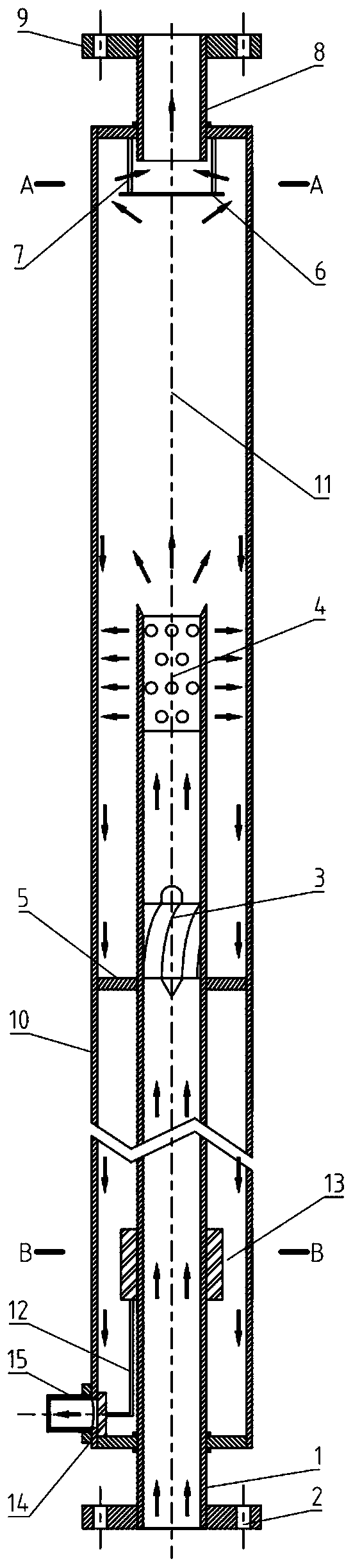
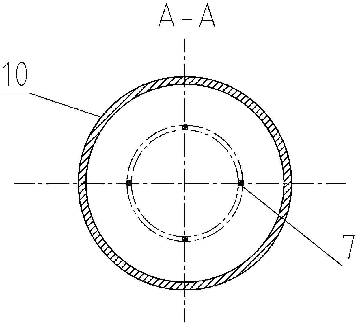
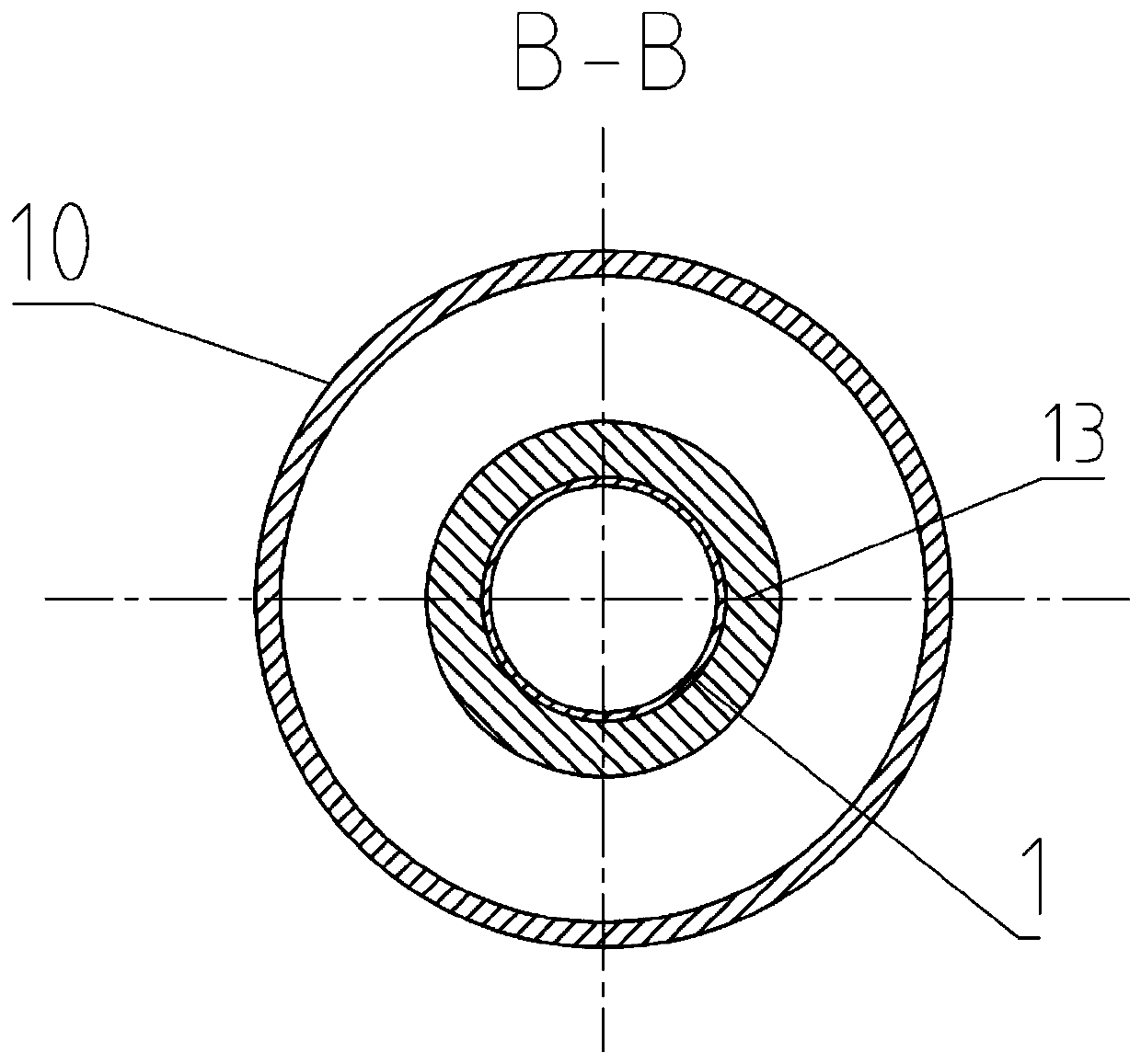
[0034] Embodiment 1: Combining Figure 1-3 , the main structure of the separator is composed of mutually nested cylinder structures, namely: the core cylinder 1, the outer cylinder 10, the separator 11, the connecting shaft 12, the movable buoy 13, the gas phase outlet 8 and the liquid phase outlet 15 of the separator They are respectively located at the top and lower part of the outer cylinder 10; a water barrier 6 is provided at the lower part of the gas phase outlet 8, and is fixed on the top cover of the outer cylinder 10 by a connecting rod 7; a liquid discharge section 4 is provided at the upper part of the core cylinder 1 to discharge A liquid discharge hole is opened in the liquid section 4; an impeller 3 is placed at the lower part of the liquid discharge section 4 in the core tube 1; A partition 11 is set and connected by a connecting shaft 12; a development section 4 to 10 times as long as the inner diameter of the core barrel 1 is reserved between the liquid discha...

Embodiment approach 2

[0046] Embodiment 2: Combining Figure 4 , on the basis of Embodiment 1, the structure of the separator is properly adjusted, and the outlet tube 17 is added, and the water blocking cap 18 is installed on the upper end of the core tube 1 through the water blocking cap support bars 19, and there is a The air outlet 17 is located inside the outer cylinder 10, the lower part of the air outlet 17 is located in the core barrel 1, the upper part of the air outlet 17 passes through the water blocking cap 18 and is located in the gravity separation chamber 11, and the upper part of the air outlet 17 is covered with a water retaining ring 16, The water retaining ring 16 is connected to the inner wall of the outer cylinder 10 . combined with Figure 4 , to further describe the implementation in detail:

[0047] combine Figure 4 , a wide-flow high-efficiency gas-liquid separator controlled by buoys provided by the present invention includes: 1 core cylinder, 2 inlet flange, 3 impelle...


PUM


Abstract

The invention aims to provide a wide-flow-path highly-efficient gas-liquid separator controlled by utilizing a buoy. The wide-flow-path highly-efficient gas-liquid separator comprises an outer cylinder and a core cylinder, wherein the upper end part of the core cylinder extends into the outer cylinder; the lower end part of the core cylinder extends out of the lower part of the outer cylinder; animpeller is arranged in the core cylinder; a liquid discharge section is arranged at the upper part of the core cylinder; a gas-phase lead-out opening is arranged at the upper end part of the outer cylinder; a water baffle plate is arranged below the gas-phase lead-out opening and fixedly arranged at the upper end part of the outer cylinder through a connecting rod; a separator liquid-phase lead-out opening is arranged at the lower end of the outer cylinder; a partition plate is arranged at the communication position of the liquid-phase lead-out opening and the interior of the outer cylinder;a movable buoy sleeves the core cylinder; the partition plate is connected with the movable buoy through a connecting shaft; an inlet flange is installed at the lower end part of the core cylinder; and an outlet flange is installed at the upper end part of the gas-phase lead-out opening. The wide-flow-path highly-efficient gas-liquid separator provided by the invention does not need a person to participate in regulation and control, and can meet the requirements of highly-efficient gas-liquid separation under the conditions of gas-liquid flow changes and different flow patterns, specifically oscillating flow patterns.

Description

technical field [0001] The invention relates to a gas-liquid separation device, in particular to a downhole gas-liquid separation device. Background technique [0002] Gas-liquid separation technology has a wide range of applications in petrochemical, energy utilization, nuclear energy development and other fields. Downhole gas-liquid separation is of great significance for oil production and prolonging the economic life of high liquid-cut wells. The gas-liquid mixture to be separated downhole has the characteristics of wide range of gas-liquid flow rate and various flow patterns. [0003] At present, a variety of high-efficiency gas-liquid separators suitable for a wide range of gas-liquid flow rates and diverse flow patterns have been proposed (“a double-barrel gas-liquid separator”, CN 110075622 A; “a wide-flow multi-flow type high-efficiency gas-liquid separator”) liquid separator", CN 110075619A; "a combined high-efficiency gas-liquid separator", CN 110075618 A; "a re...

Claims


Application Information

Patent Timeline
Patent Type & Authority Applications(China)
IPC IPC(8): B01D45/02B01D45/08B01D45/14
CPCB01D45/02B01D45/08B01D45/14
Inventor 阎昌琪曾晓波赵伟光范广铭赵乐祝福强侯明文
Owner HARBIN ENG UNIV
Why Eureka
Try Eureka