
Automotive animated image projector and method of operation

a projector and animated technology, applied in the field of automotive animated image projectors, can solve the problems of increasing the complexity and size of the apparatus, the impracticality of simple animations, and the impracticality of gobo projectors for projecting complex animations and video, and achieves the effect of more flexibility and choice in the position of the projector

Inactive Publication Date: 2019-04-04
GRAKON LLC
View PDF10 Cites 11 Cited by
  • Summary
  • Abstract
  • Description
  • Claims
  • Application Information

AI Technical Summary

Benefits of technology

The patent text discusses a feature of a small automotive image projector that allows for flexibility in mounting options. However, with smaller housing sizes, it can be more difficult to maintain the projector's operating temperature within a safe range without using additional cooling measures. The technical effect of this patent is to provide a solution for heat dissipation challenges associated with smaller microelectromechanical system projectors in automotive settings.

Problems solved by technology

However, because different projectors are needed for each individual image, it is only practical for simple animations that are limited to the images provided on the gobo or other gobo-like optical component.
However, if more than one optical component is used for each projector, this necessitates a mechanism for switching optical components, which adds to the complexity and size of such an apparatus.
This makes gobo projectors impractical for projecting complex animations and video.
To install a puddle lamp in the side mirror housing it is desirable for the puddle lamp apparatus to be compact in size, which is problematic for an apparatus that uses a plurality of projectors.
An alternative location for mounting puddle lamps is on the chassis below the vehicle body, but a drawback of locations closer to the ground is that the apparatus can be exposed to a harsher environment where it might be more likely to be covered in dirt and / or hit by rocks or knocked by obstacles on the road.

Method used


Image

  • Automotive animated image projector and method of operation
  • Automotive animated image projector and method of operation
  • Automotive animated image projector and method of operation

Examples


Embodiment Construction

[0035]Reference is now made in detail to the present preferred embodiments, examples of which are illustrated in the accompanying drawings. Whenever possible, the same reference numerals are used throughout the drawings to refer to the same parts, and if the parts are the same and indicated by the same reference numeral, for brevity such parts may not be re-introduced and described with respect to each drawing. If the parts are not the same, but similar in function, like reference numerals are used.

[0036]The following detailed description represents embodiments that are intended to provide an overview or framework for understanding the nature and character of the claims. The accompanying drawings are included to provide further understanding of the claims and constitute part of the specification. Accordingly, the detailed descriptions and drawings are non-limiting to the scope of what is claimed and are intended to illustrate and explain the principles and operations of these embodi...


PUM


Abstract

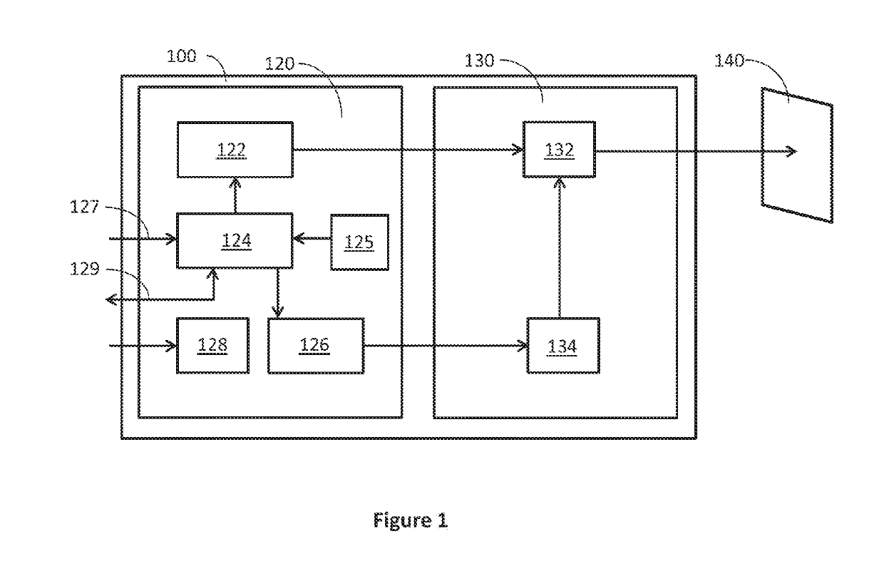
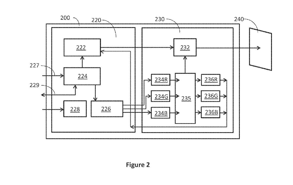
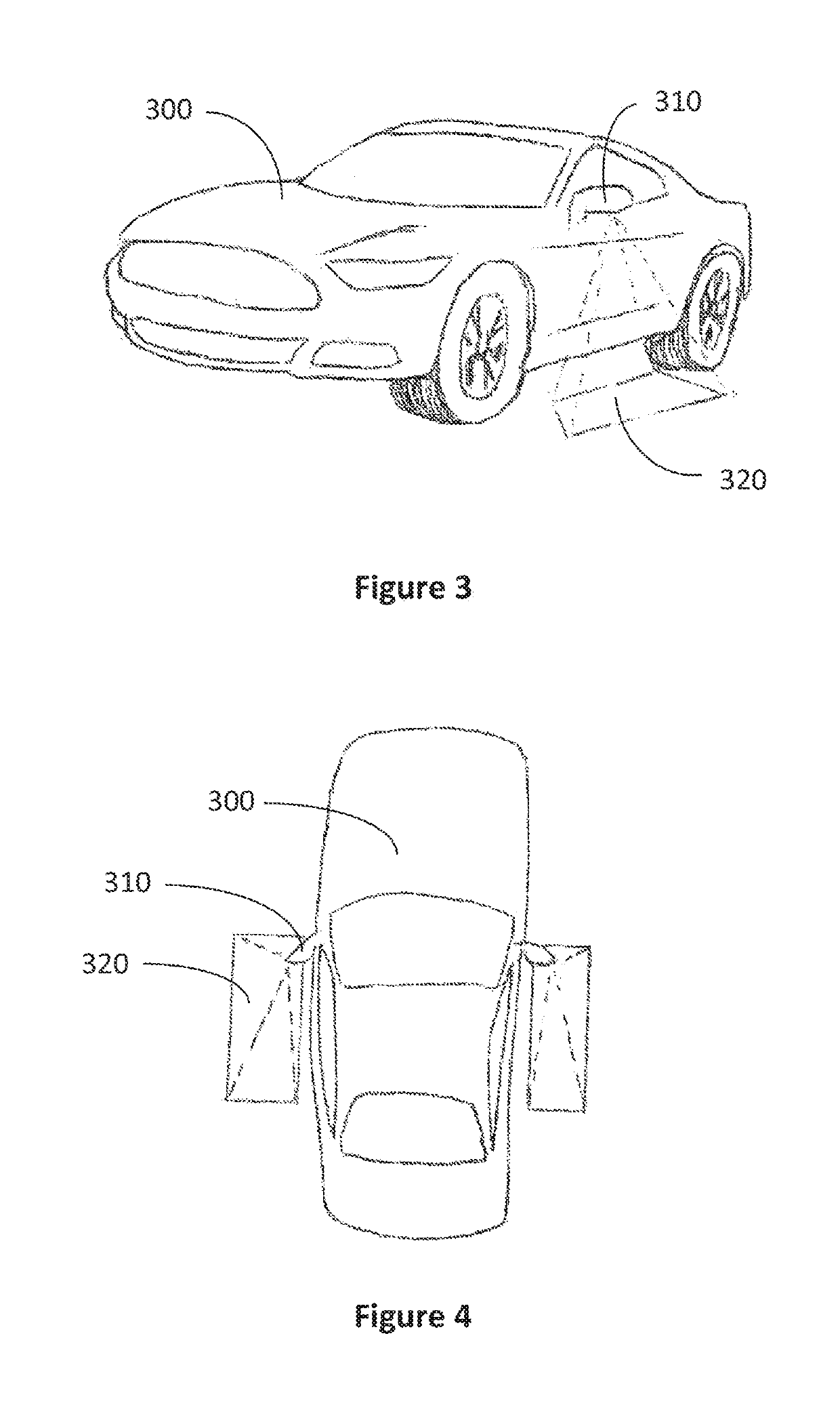
An automotive animated image projector comprises a light source emitting a light beam, a microelectromechanical system projector aligned to receive the light beam and project an animated image onto a target surface, a computer system programmed to control the light source and the microelectromechanical system with commands to produce the animated image, and a transmission link for sending the commands from the computer system to the light source and the microelectromechanical system projector. In some embodiments, the target surface is the ground next to a vehicle and the animated image illuminates the ground to assist entry into, and exit from, the vehicle. A method is also provided of projecting an animated image from an automotive animated image projector. The method comprises generating a light beam, directing the light beam onto a microelectromechanical system projector, manipulating the light beam by dynamically controlling the microelectromechanical system projector to generate animated images that are projected onto a target surface.

Description

CROSS-REFERENCE TO RELATED APPLICATIONS[0001]This application claims priority to U.S. Provisional Patent Application Nos. 62 / 567,082 filed on Oct. 2, 2017 the content of which is herein incorporated by reference in its entirety.BACKGROUND OF THE INVENTIONField of the Invention[0002]The present application relates to an automotive animated image projector and a method of operating same. More particularly, the automotive animated image projector is mounted to a vehicle and projects an animated image on the ground next to the vehicle or onto the vehicle itself or onto an interior surface of the vehicle.Description of Related Art[0003]The automotive industry often blends functional features with aesthetic features to distinguish products from competitors and to make their products more desirable. One area where advancements have been made in recent years is lighting. This is because new lighting technologies offer more capabilities in what the lighting can do, how it looks, and where it...

Claims


Application Information

Patent Timeline
IPC IPC(8): H04N9/31
CPCH04N9/3102H04N9/3141H04N9/3161H04N9/3129H04N9/3132H04N9/3179H04N9/3194B60K35/00B60Q1/2665B60Q2400/50B60Q1/323B60Q3/41B60Q3/60B60Q3/80B60Q1/247B60K35/28B60K2360/165B60K2360/23B60K2360/334B60K35/60B60K2360/771B60K2360/785B60K2360/794B60K2360/797
Inventor MEDVEC, MICHAELMANDERVILLE, LORENZO F.MILLER, ROBERT H.MEASEL, ERIK LEE
Owner GRAKON LLC
Learn More