Multi-aperture imaging device, imaging system and method for capturing an object area

Active Publication Date: 2019-04-04
FRAUNHOFER GESELLSCHAFT ZUR FOERDERUNG DER ANGEWANDTEN FORSCHUNG EV
View PDF3 Cites 10 Cited by
  • Summary
  • Abstract
  • Description
  • Claims
  • Application Information

AI Technical Summary

Benefits of technology

The present invention is about a new way to capture images using optical channels that project different parts of an object area onto different image sensor areas. This means that a single optics can be used to capture multiple partial object areas, reducing the number of optics needed and making the optics array smaller. In one embodiment, a multi-aperture imaging device has been developed that uses at least three optics to capture an object area. This allows for both 3D captures and higher resolution using superresolution. Additionally, the imaging system includes a housing that is flat and minimal in thickness, allowing for a more compact and cost-effective design.

Problems solved by technology

Conventional cameras transmit the total field of view in one channel and are limited as regards to miniaturization.

Method used


Image

  • Multi-aperture imaging device, imaging system and method for capturing an object area
  • Multi-aperture imaging device, imaging system and method for capturing an object area
  • Multi-aperture imaging device, imaging system and method for capturing an object area

Examples


Embodiment Construction

[0082]Before embodiments of the present invention will be discussed in detail below with reference to the drawings, it should be noted that identical, functionally equal or equal elements, objects and / or structures in the different figures are provided with the same reference numbers, such that the descriptions of these elements illustrated in the different embodiments are inter-exchangeable or inter-applicable.

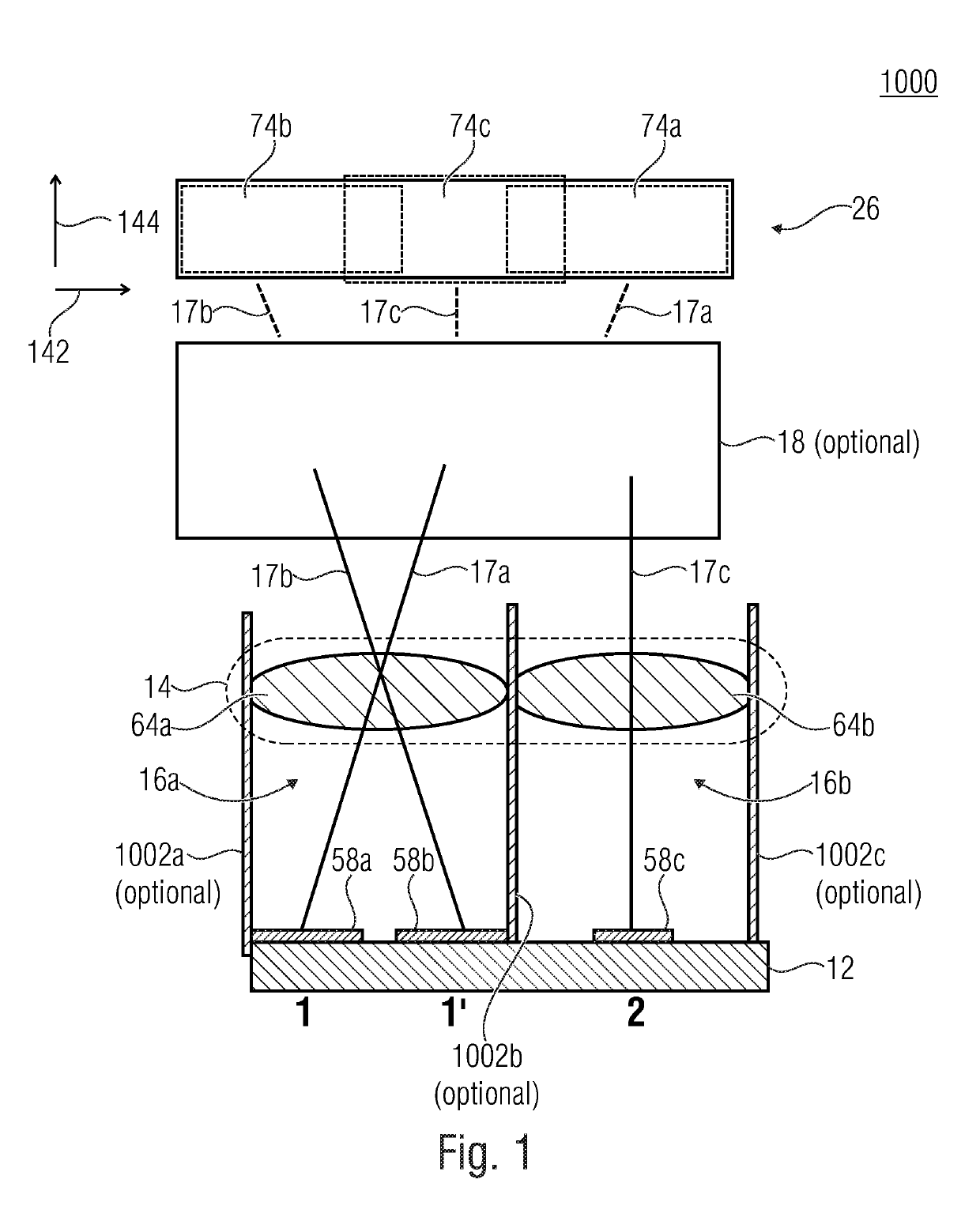
[0083]FIG. 1 shows a schematic top view of a multi-aperture imaging device 1000 according to an embodiment. The multi-aperture imaging device 1000 can be a device that is configured to capture an object area (field of view) 26 in the form of several partial object areas (partial fields of view) 74a-c. The captured partial object areas 74a-c can be assembled to a total image by the device 1000 or a downstream computing device, such as processor, a field programmable gate array (FPGA), a CPU (central processing unit), and hardware specific for the method, such as an ASIC or the...


PUM


Abstract

A multi-aperture imaging device includes at least one image sensor and an array of juxtaposed optical channels. Each optical channel includes optics for imaging of projecting at least one partial area of an object area on an image sensor area of the image sensor. A first optics of a first optical channel is configured to project a first partial area of the object area on a first image sensor area and to project a second partial area of the object area on a second image sensor area. A second optics of a second optical channel is configured to project at least a third partial area of the object area on a third image sensor area. The first partial area and the second partial area are disjoint in the object area. The third partial area overlaps incompletely with the first partial area.

Description

CROSS-REFERENCES TO RELATED APPLICATIONS[0001]This application is a continuation of copending International Application No. PCT / EP2016 / 082478, filed Dec. 22, 2016, which is incorporated herein by reference in its entirety, and additionally claims priority from German Application No. DE 10 2016 200 285.6, filed Jan. 13, 2016, which is incorporated herein by reference in its entirety.[0002]The present invention relates to a multi-aperture imaging device, to an imaging system with a multi-aperture imaging device, for example, a mobile phone and to a method for capturing an object area. Further, the present invention relates to a multi-aperture imaging device and an image system with a channel imaging system with channel-wise usage of several non-contiguous image areas.BACKGROUND OF THE INVENTION[0003]Conventional cameras transmit the total field of view in one channel and are limited as regards to miniaturization. In smartphones, two cameras are used that are oriented in and opposite t...

Claims


Application Information

Patent Timeline
IPC IPC(8): H04N5/225H04N5/232G02B13/00
CPCH04N5/2258H04N5/23212G02B13/0015H04N13/239H04N23/45H04N23/698H04N23/55H04N23/67
Inventor WIPPERMANN, FRANKBRUECKNER, ANDREASREIMANN, ANDREAS
Owner FRAUNHOFER GESELLSCHAFT ZUR FOERDERUNG DER ANGEWANDTEN FORSCHUNG EV
Why Eureka
Try Eureka