
Aerobic wastewater treatment system

a wastewater treatment system and anaerobic technology, applied in biological water/sewage treatment, sustainable biological treatment, separation processes, etc., can solve the problems of degeneration of the treatment process, inability to treat sewage in the septic tank, and inability to meet the needs of treatment, so as to reduce the number of pathogenic bacteria

Inactive Publication Date: 2019-03-28
TITTLEBAUM MARTY +1
View PDF3 Cites 0 Cited by
  • Summary
  • Abstract
  • Description
  • Claims
  • Application Information

AI Technical Summary

Benefits of technology

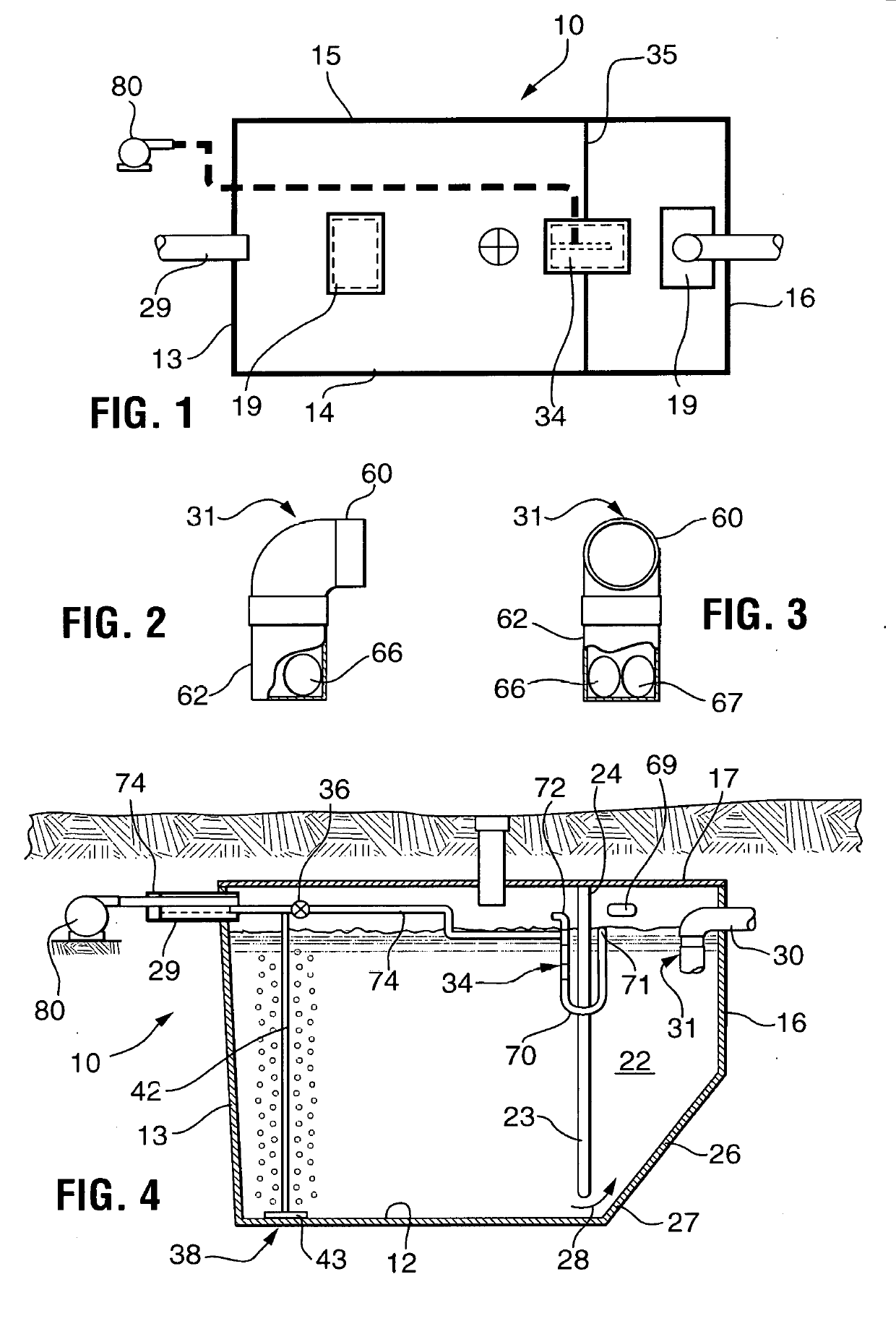
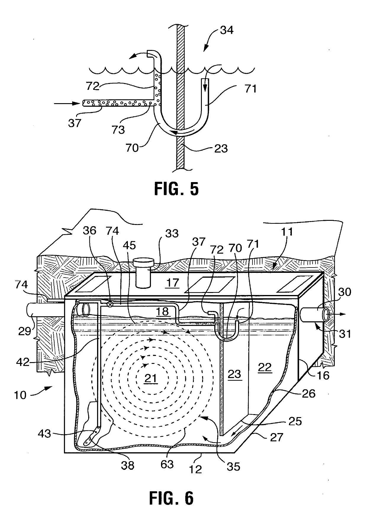
The system described in this patent produces a clear and odorless effluent that meets state discharge standards. It uses a single tank and an extended aeration system activated by oxygen and organic matter in the waste stream. The aeration system maintains optimal conditions for the growth of beneficial micro-organisms that convert organic materials into gases and cell material. This results in a significant reduction of pathogenic bacteria. After about 24 hours, the mixture enters a clarifier where the separated micro-organisms are returned to the aeration zone and the treated wastewater is discharged through the launder assembly. The system is controlled to maintain the quiescent conditions of the clarifier and may be discharged to an approved point of discharge.

Problems solved by technology

There are two major problems with septic tanks.
Septic tanks do not do a good job of treating the sewage.
When the soil is in a condition that sub-surface discharge is not possible or allowed, pollution of the ground water or polluting surface waters can occur.
In some aerated treatment systems, there is a problem of clogging of the aeration assembly, or diffuser, which provides oxygen and mixing to the unit.
Such clogging will cause a degeneration of the treatment process or possibly a total stoppage of air flow to the vessel, converting the process conditions from aerobic to anaerobic, thus removing most of the treatment capability.
Also, some aeration assemblies are prone to movement within the vessel, due to the particular design of the assembly and the flexibility of the piping used in construction.
Movement of the aeration assembly is unwanted for two primary reasons.
Perhaps the most troublesome problems encountered by prior art systems, however, are those pertaining to the accumulation of scum or floating material near the effluent line.
While that device did serve to reduce the solids within the effluent more effectively than its predecessors, environmental laws are becoming increasingly more strict, requiring even further reductions in the amount of solids leaving such treatment systems.

Method used


Image

  • Aerobic wastewater treatment system
  • Aerobic wastewater treatment system

Examples


Embodiment Construction

[0039]The terminology used herein is for the purpose of describing particular example embodiments only and is not intended to be limiting. As used herein, the singular forms “a,”“an,” and “the” may be intended to include the plural forms as well, unless the context clearly indicates otherwise. The terms “comprises,”“comprising,”“including,” and “having,” are inclusive and therefore specify the presence of stated features, integers, steps, operations, elements, and / or components, but do not preclude the presence or addition of one or more other features, integers, steps, operations, elements, components, and / or groups thereof. The method steps, processes, and operations described herein are not to be construed as necessarily requiring their performance in the particular order discussed or illustrated, unless specifically identified as an order of performance. It is also to be understood that additional or alternative steps may be employed.

[0040]When an element or layer is referred to...


PUM

PropertyMeasurementUnit
distanceaaaaaaaaaa
flow rateaaaaaaaaaa
exit velocityaaaaaaaaaa

Abstract

A wastewater treatment system consisting of a single tank extended aeration activated sludge process which is capable of producing a clear odorless effluent which meets applicable state discharge standards.

Description

CROSS REFERENCES TO RELATED APPLICATIONS[0001]This application claims priority from U.S. Provisional Application Ser. No. 62 / 534,800 filed on Jul. 20, 2017.TECHNICAL FIELD[0002]The present invention relates to wastewater systems, and especially to those wastewater treatment systems which are packaged, containerized units.BACKGROUND OF THE INVENTION[0003]Many new subdivisions are being developed on sewage collection and treatment processes utilizing on-site sewage treatment units. Many people build homes or place manufactured homes on lots not serviced by municipal sewage collection systems.[0004]In the treatment of wastewater, there is often utilized a containerized or packaged unit treatment plant which treats received wastewater on an intermittent or small flow basis, such as from a home, small apartment building, or the like. In the home construction industry, for example, a buried, subsoil sewage treatment vessel or septic tank is often used for primary treatment of wastewater n...

Claims


Application Information

Patent Timeline
Patent Type & Authority Applications(United States)
IPC IPC(8): C02F3/20C02F1/40
CPCC02F3/201C02F1/40C02F2001/007C02F2209/42C02F2203/006C02F1/006C02F3/1242C02F2201/007C02F2301/026Y02W10/10
Inventor TITTLEBAUM, MARTYTUCKER, GRADY
Owner TITTLEBAUM MARTY
Learn More