Multi-link suspension for multi-hulled vessels

a multi-link suspension and multi-hull technology, applied in the direction of hulls, vessel construction, movement controllers, etc., can solve the problems of reduced lateral spacing between the hulls, limited vessel speed, and inability to provide a strong control of the yaw of the hydrofoil relative to the body portion, and achieve different stiffness

Active Publication Date: 2019-03-28
NAUTI CRAFT PTY LTD
View PDF0 Cites 4 Cited by
  • Summary
  • Abstract
  • Description
  • Claims
  • Application Information

AI Technical Summary

Benefits of technology

The patent describes a vehicle design that allows for a compact and stable ride while still providing anti-dive or anti-squat properties. The design includes a chassis that can adjust its length and height, and a set of supports that can adjust their stiffness in different directions. This allows for better control and adjustment of the vehicle's suspension modes. Overall, the design allows for a more versatile and comfortable ride on different terrains.

Problems solved by technology

However with such marine vessels having a chassis or body portion at least partially suspended relative to multiple hulls, regardless of whether the chassis engages the water or not, there is a design compromise in the width of the vessel between the hulls being laterally spaced wide apart for passive roll stiffness and the hulls being laterally spaced close together to make the vessel footprint narrow for negotiating confined spaces such as ports or marinas and / or for transportation on a trailer.
However, the lateral spacing between the hulls is decreased when the chassis is raised, which is an undesirable combination for stability.
However vessel speed can be limited by wave impacts, so the rougher the sea state the larger the requirement for the height under the chassis.
However there is only one suspension locating linkage for each hydrofoil to locate it relative to the body portion which does not provide a strong control of the yaw of the hydrofoil relative to the body portion.

Method used


Image

  • Multi-link suspension for multi-hulled vessels
  • Multi-link suspension for multi-hulled vessels
  • Multi-link suspension for multi-hulled vessels

Examples


Embodiment Construction

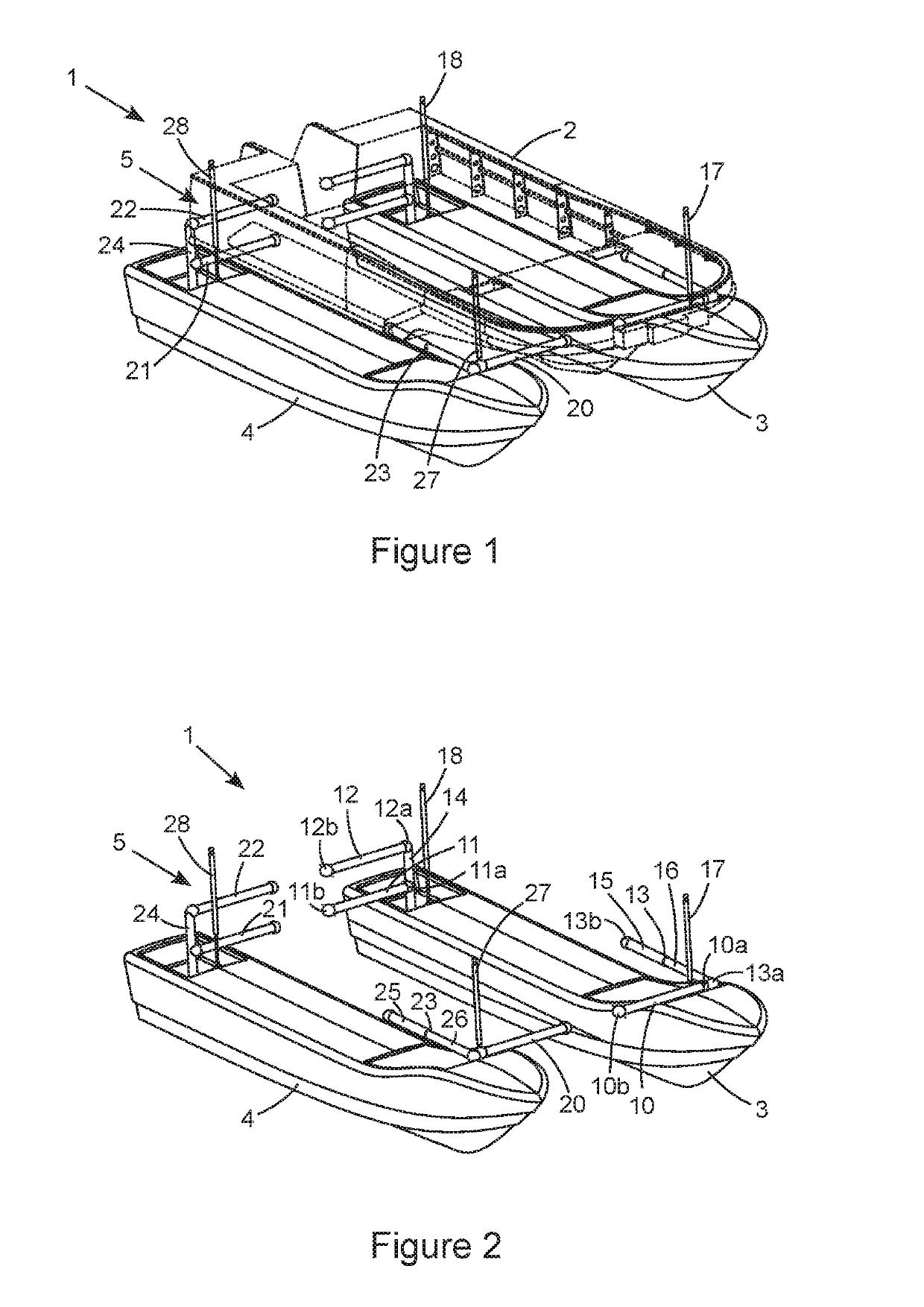
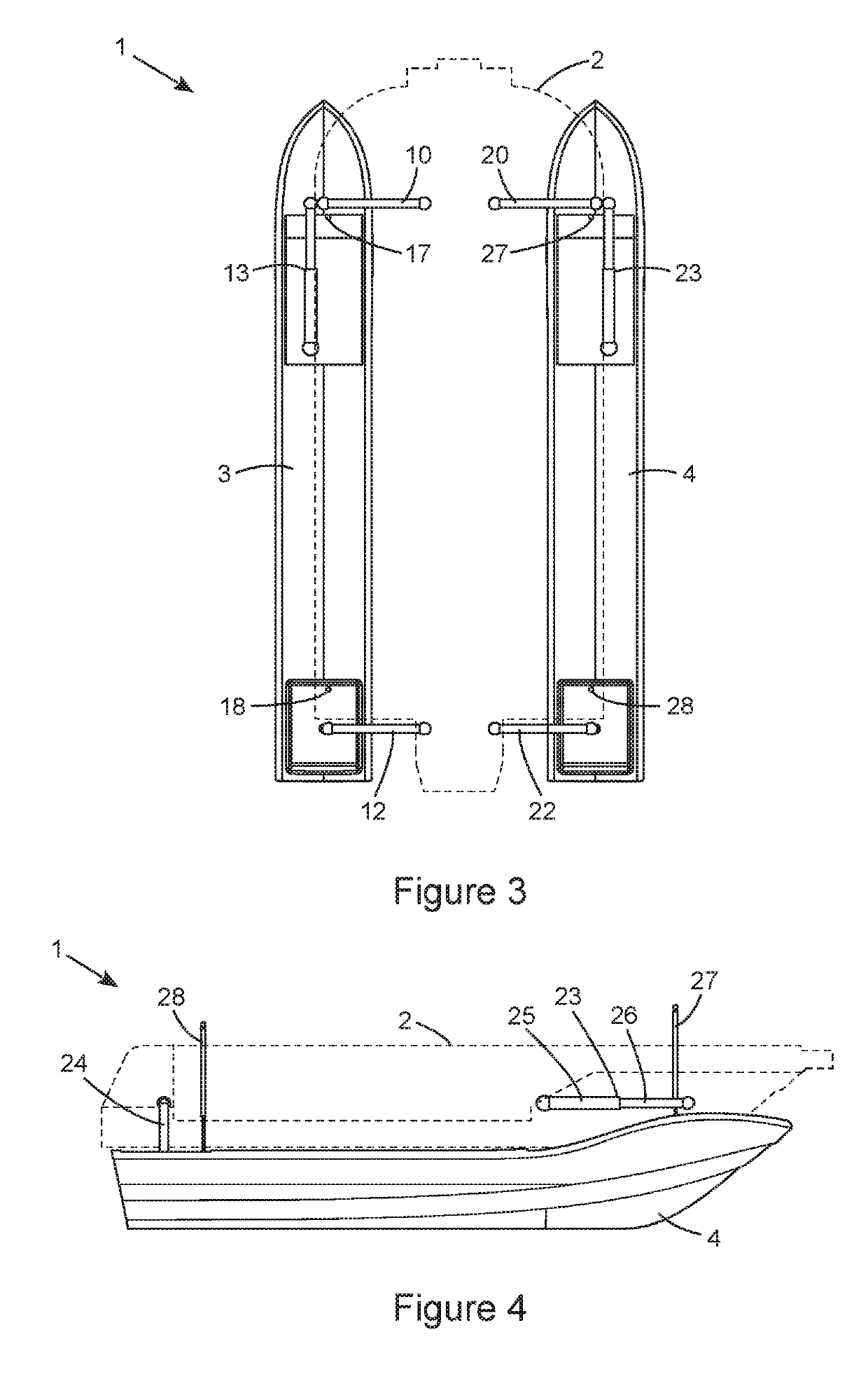
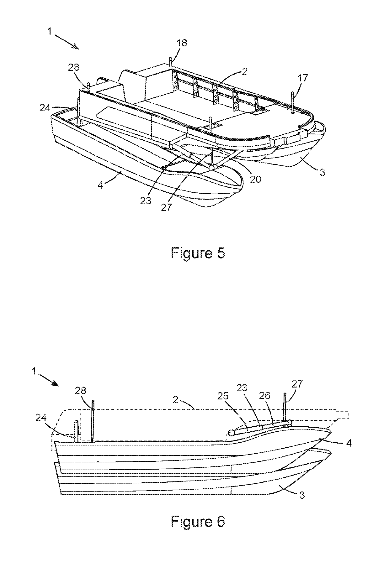
[0056]Referring initially to FIG. 1, there is shown a water craft 1 having a body portion or chassis 2 shown in dashed lines and transparency to enable the left and right hulls 3 and 4 and the suspension system 5 to be more revealed. Throughout the specification where the term chassis is used it is referring to the structure to which the hulls are located by the suspension system and can be interchangeable with the term body portion. The chassis can be a simple platform or include gunwales, a passenger cabin, cargo area. For example, as in automotive use, the chassis can be a ladder frame, or it can combine a ladder frame with a fixed cabin where the suspension loads are primarily input into the ladder frame, or it can be a monocoque where the suspension loads are input into a shell structure including the cabin. The water craft is shown at ride height, i.e. somewhere between the maximum and minimum height of the chassis above the hulls, typically between 30 and 70% of that total tr...


PUM


Abstract

A suspension system for a water craft, the water craft including a chassis which is at least partially suspended above or relative to at least a first hull and a second hull. The suspension system includes a first hull locating arrangement for at least partially constraining the first hull in a lateral, a yaw, a roll and a longitudinal direction relative to the chassis, the first hull locating arrangement comprising a first, a second, a third and a fourth link arranged to directly or indirectly connect between the hull and the chassis. The first, second and third links each extend in at least a lateral direction relative to the chassis and contribute to a lateral constraint on the first hull relative to the chassis. The second link is longitudinally spaced from the first link relative to the chassis to contribute to a hull yaw constraint on the first hull relative to the chassis. The third link is vertically spaced from the first and / or second link to contribute to a hull roll constraint on the first hull relative to the chassis. The fourth link extends in at least a longitudinal direction relative to the chassis to at least contribute to a longitudinal constraint on the first hull relative to the chassis and may be adjustable in length to vary the lateral spacing between the first and second hulls and thereby vary the overall width of the vessel.

Description

TECHNICAL FIELD[0001]The present invention relates to multi-hulled water craft and specifically relates to the location of a movable hull.BACKGROUND[0002]Marine vessels including multiple hulls can include suspension for locating and controlling the position of at least one of the hulls relative to the chassis or body portion. For example, U.S. Pat. No. 7,314,014 discloses a water craft having a body portion suspended above four hulls, each hull being located relative to the body portion by a single wishbone suspension linkage arrangement.[0003]U.S. Pat. No. 5,228,404 discloses a trimaran where the chassis is supported above three hulls, each being movable relative to the chassis. The three hulls comprise a left hull, a right hull and a rear central hull, all three hulls being interconnected by a lateral bar about which they are individually pivoted. The rear centre hull has two laterally spaced rearward trailing arms and a forwardly spaced central trailing arm, all three trailing a...

Claims


Application Information

Patent Timeline
IPC IPC(8): B63B39/00B63B1/14
CPCB63B39/00B63B1/14B63B2001/145B63B1/10B63B7/00B63B17/0081B63B39/005
Inventor LONGMAN, MICHAEL JAMESMONK, RICHARD
Owner NAUTI CRAFT PTY LTD
Why Eureka
Try Eureka