Control apparatus for vehicular power transmitting system

a control apparatus and transmission system technology, applied in the field of control apparatuses, can solve the problem that the transmission system does not have a sufficiently high degree of control response of switching, and achieve the effect of reducing the risk of generation of shifting shock upon switching the transmission system between the first and second drive modes, reducing the speed of the rotary motion of the engine, and reducing the risk of shifting shock

Active Publication Date: 2019-03-21
TOYOTA JIDOSHA KK
View PDF4 Cites 7 Cited by
  • Summary
  • Abstract
  • Description
  • Claims
  • Application Information

AI Technical Summary

Benefits of technology

[0016]According to the fourth mode of the invention, the control apparatus for the vehicular power transmitting system is configured such that the power transmission switching portion selectively establishes one of: the first drive mode in which the rotary motion of the engine is output from the output shaft such that the speed of the rotary motion of the engine is reduced with respect to the rotating speed of the output shaft; the second drive mode in which the rotary motion of the engine is output from the output shaft such that the speed of the rotary motion of the engine is raised with respect to the rotating speed of the output shaft; and the third drive mode in which the rotary motion of the engine is output from the output shaft such that the speed of the rotary motion of the engine is equal to the rotating speed of the output shaft. Accordingly, the vehicular power transmitting system is switched between the first and second drive modes, through the third drive mode. The vehicular power transmitting system can be switched from the third drive mode to the first or second drive mode by simply bringing one of the first and second coupling elements into its released state, so that a change of the operating speed of the engine can take place smoothly without a discomfort being given to the vehicle operator when the vehicular power transmitting system is switched between the first and second drive modes, whereby the risk of generation of the shifting shock upon switching of the vehicular power transmitting system between the first and second drive modes can be reduced. In addition, where the predetermined condition described above is satisfied, the vehicular power transmitting system can be switched with the concurrent engaging and releasing actions of the first and second coupling elements, with a high degree of switching response, between the first drive mode and second drive mode.
[0017]According to the fifth mode of the invention, the control apparatus for the vehicular power transmitting system is configured to control the vehicular power transmitting system having a plurality of assignment patterns in each of which plurality overall speed positions are assigned to the first, second and third drive modes. In this fifth mode of the invention, the power transmission switching portion switches the vehicular power transmitting system between the first and second drive modes through the third drive mode when the assignment pattern in which at least one of the overall speed positions is assigned to the third drive mode is selected, and switches the vehicular power transmitting system between the first and second drive modes with the concurrent engaging and releasing actions of the first and second coupling elements when the assignment pattern in which none of the overall speed positions is assigned to the third drive mode is selected. In a running state of the vehicle requiring a high degree of fuel economy, the assignment pattern in which at least one of the overall speed positions is assigned to the third drive mode is selected, and the vehicular power transmitting system is shifted between the first and second drive modes, through the third drive mode, so that a risk of generation of a shifting shock upon switching between the first and second drive modes is reduced. In a running state of the vehicle requiring a high degree of acceleration response, the assignment pattern in which none of the overall speed positions is assigned to the third drive mode is selected, and the vehicular power transmitting system is shifted between the first and second drive modes, with the concurrent engaging and releasing actions of the coupling elements, so that a control response of switching between the first and second drive modes can be improved.
[0018]According to the sixth mode of the invention, the control apparatus for the vehicular power transmitting system is configured such that the power transmission switching portion switches the vehicular power transmitting system between the first and second drive modes, on the basis of the required vehicle drive force represented by the amount of operation of the accelerator pedal, and the running speed of the vehicle, and according to the predetermined drive mode switching map having the switching boundary line. When the sporty drive mode is selected, the power transmission switching portion moves the switching boundary line in at least one of the direction in which the running speed is raised, and the direction in which the required vehicle drive force (or applied load) is reduced. Namely, the switching boundary line is moved in both or either one of the direction in which the vehicle running speed is raised and the direction in which the required vehicle drive force is reduced. Thus, the switching boundary line is moved such that the area in which the first drive mode is selected is enlarged when the sporty drive mode is selected, so that the driving performance of the vehicle is improved in the sporty drive mode, owing to the concurrent engaging and releasing actions of the first and second coupling elements.

Problems solved by technology

Since the power transmitting system is once placed in the fixed speed position for synchronization of the rotating speeds of the rotary elements, the power transmitting system does not have a sufficiently high degree of control response of switching from one of the split modes to another.

Method used


Image

  • Control apparatus for vehicular power transmitting system
  • Control apparatus for vehicular power transmitting system
  • Control apparatus for vehicular power transmitting system

Examples


first embodiment

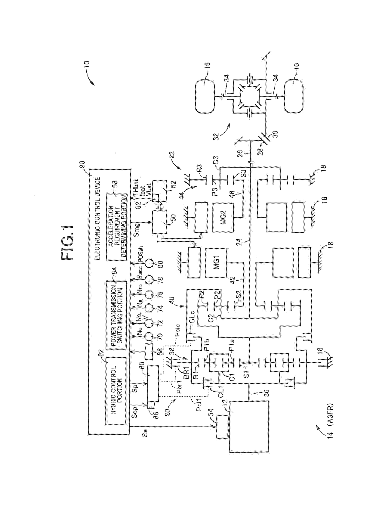
[0083]Reference is first made to FIG. 1, which is the schematic view showing an arrangement of a power transmitting system 14 of a vehicle 10 according to a first embodiment of this invention, which has a gear train A3FR and which is controlled by a control apparatus according to the present invention, and major control portions of the control apparatus. As shown in FIG. 1, the vehicle 10 is a hybrid vehicle provided with an engine 12, a first motor / generator MG1, a second motor / generator MG2, the above-indicated power transmitting system (vehicular power transmitting system) 14, and drive wheels 16. The engine 12, first motor / generator MG1 and second motor / generator MG2 may be used as a vehicle drive power source.

[0084]The engine 12 is a known internal combustion engine such as a gasoline engine or a diesel engine, which generates a drive force by combustion of a suitable fuel. The engine 12 is controlled by the control apparatus in the form of an electronic control device 90 descr...

second embodiment

[0154]Other embodiments of this invention will be described. It is to be understood that the same reference signs will be used in the following embodiments, to identify the corresponding elements, which will not be described redundantly.

[0155]FIG. 25 is the view similar to that of FIG. 20, showing an example of a drive mode switching map used to change the sub-modes of the HV drive mode such that the electric power amount SOC stored in the battery unit 52 is held constant. This drive mode switching map has a normal driving performance switching boundary line (solid line), a first high driving performance switching boundary line (two-dot chain) and a second high driving performance switching boundary line (broken line), which are used for switching the vehicular power transmitting system 14 between the O / D input split HV drive sub-mode (second drive mode) of FIG. 13 to be established in the engaged state of the clutch CLc, and the U / D input split HV drive sub-mode (first drive mode) ...

third embodiment

[0160]FIG. 29 is the view showing a drive mode switching map used to change the HV drive mode among the U / D input split HV drive sub-mode (first drive mode), the O / D input split HV drive sub-mode (second drive mode), and the fixed-speed-position engine-drive-force-input HV drive sub-mode (third drive mode), such that the amount of electric power stored in the battery unit 52 is held constant. In the drive mode switching map of FIG. 29, first through eighth overall speed positions are assigned to the U / D input split HV drive sub-mode, the O / D input split HV drive sub-mode, and the fixed-speed-position direct-engine-force-input sub-mode. FIG. 30 is the view showing a drive mode switching map used to change the HV drive mode among drive mode among the U / D input split HV drive sub-mode (first drive mode), the O / D input split HV drive sub-mode (second drive mode), and the fixed-speed-position engine-drive-force-input HV drive sub-mode (third drive mode), such that the electric power stor...


PUM


Abstract

A control apparatus for a vehicular power transmitting system includes a power transmission switching portion configured to selectively establish a first drive mode by placing one of the first and second coupling elements in an engaged state, a second drive mode by placing the other of the first and second coupling elements in an engaged state, or a third drive mode by placing both of the first and second coupling elements in the engaged states. The power transmission switching portion switches the vehicular power transmitting system between the first and second drive modes through the third drive mode, where a predetermined condition is not satisfied, and switches the vehicular power transmitting system between the first and second drive modes with concurrent engaging and releasing actions of the first and second coupling elements, where the predetermined condition is satisfied.

Description

[0001]This application claims priority from Japanese Patent Application No. 2017-181647 filed on Sep. 21, 2017, the disclosure of which is herein incorporated by reference in its entirety.FIELD OF THE INVENTION[0002]The present invention relates to a control apparatus for a vehicle provided with a first differential mechanism to which an engine is operatively connected in a power transmittable manner, a second differential mechanism a differential state of which is controlled by controlling an operating state of a first motor / generator, and a second motor / generator operatively connected in a power transmittable manner to an output rotary member connected to drive wheels, and more particularly to a control technique for improving a control response of switching the vehicle from one of different drive modes to another.BACKGROUND OF THE INVENTION[0003]US-2009-0118936A discloses an example of a known vehicular power transmitting system provided with: a power transmitting mechanism throu...

Claims


Application Information

Patent Timeline
Patent Type & Authority Applications(United States)
IPC IPC(8): B60W20/10B60K6/26B60W30/182B60K6/365B60K6/547
CPCB60W20/10B60K6/26B60W30/182B60K6/365B60K6/547B60Y2200/92B60Y2300/182B60W2710/0644B60Y2400/73B60K6/387B60K6/445B60K2006/381B60W10/02B60W10/06B60W10/08B60W10/10B60W10/115B60W20/00B60W20/30B60W20/40Y02T10/62
Inventor YAMAMOTO, MASAFUMITABATA, ATSUSHIIMAMURA, TATSUYAOKUDA, KOICHIFUJII, KOTA
Owner TOYOTA JIDOSHA KK
Why Eureka
Try Eureka