
Straddle vehicle

a technology of straddle vehicles and crankcases, which is applied in the direction of transportation and packaging, cycle equipment, and bicycle stands, etc., can solve the problem that the gear position sensor cannot be smoothly mounted on the crankcase, and achieve the effect of convenient work

Active Publication Date: 2019-03-14
KAWASAKI MOTORS LTD
View PDF8 Cites 0 Cited by
  • Summary
  • Abstract
  • Description
  • Claims
  • Application Information

AI Technical Summary

Benefits of technology

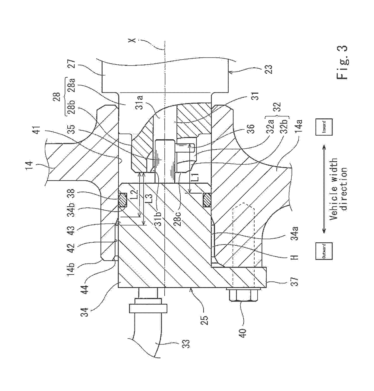
The present invention addresses the problem of preventing position deviation between the gear position sensor and the shift drum in a configuration where a seal ring is used to seal the space between the outer surface of the gear position sensor and the inner surface of the insertion hole. The invention provides a solution that allows for easy insertion of the gear position sensor into the insertion hole while keeping the angle of the engagement part and the engaged part within a certain range, and without causing high insertion resistance or position deviation between the gear position sensor and the shift drum around the axis line. The seal ring is gradually pressed in a radial direction, making the work of inserting the gear position sensor easier, and the clearance in the circumferential direction is formed to allow for easy movement of the gear position sensor around the axis line. Overall, the invention simplifies the process of inserting the gear position sensor into the insertion hole and improves the accuracy of the positioning of the gear position sensor.

Problems solved by technology

As a result, the gear position sensor cannot be smoothly mounted on the crankcase.

Method used


Image

  • Straddle vehicle
  • Straddle vehicle
  • Straddle vehicle

Examples


Embodiment Construction

[0024]Hereinafter, the embodiment of the present invention will be described with reference to the drawings. The stated directions are from the perspective of a rider R straddling the motorcycle.

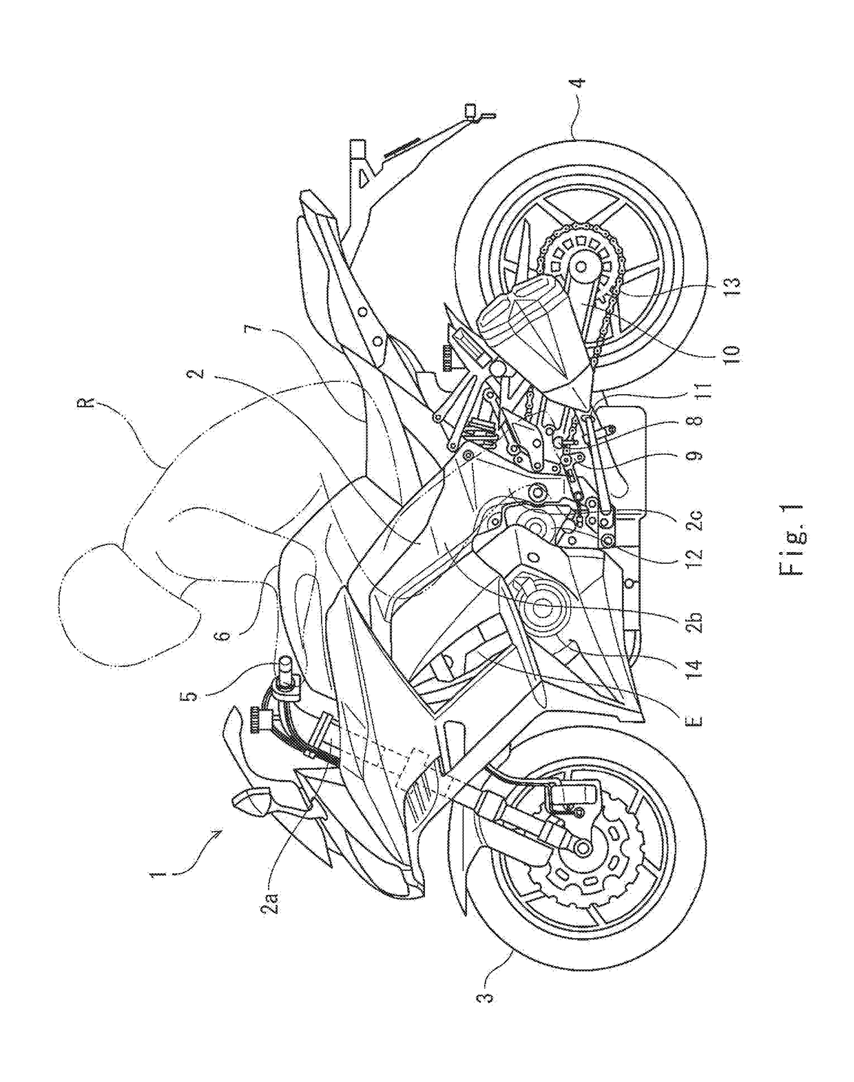
[0025]FIG. 1 is a left side view of a motorcycle according to an embodiment. As shown in FIG. 1, a motorcycle 1 which is an example of a straddle vehicle includes a vehicle body frame 2, a front wheel 3 mounted on the vehicle body frame 2, and a rear wheel 3 mounted on the vehicle body frame 2. The front wheel 3 is a driven wheel, and the rear wheel 4 is a drive wheel. The vehicle body frame 2 includes a head pipe 2a, a main frame 2b extending rearward from the head pipe 2a, and a pivot frame 2c connected to the rear portion of the main frame 2b. A steering shaft (not shown) is coupled to a bar-type handle 5 which can be gripped by a rider R. The head pipe 2a supports the steering shaft in such a manner that the steering shaft is rotatable. The steering shaft is rotated, and thus the front w...


PUM


Abstract

A straddle vehicle comprises a shift drum formed with an engaged part; a transmission case formed with an insertion hole, a gear position sensor including an engagement part engageable with the engaged part; and a seal ring fitted to the outer peripheral surface of the gear position sensor, and the insertion hole includes a first inner peripheral surface with which the seal ring is in tight contact in a state in which the engagement part is engaged with the engaged part, and a second inner peripheral surface located closer to an entrance of the insertion hole than the first inner peripheral surface and having a diameter larger than a diameter of the first inner peripheral surface, and in a state in which the seal ring has reached an entrance of the first inner peripheral surface, at least a portion of the engagement part is fitted to the engaged part.

Description

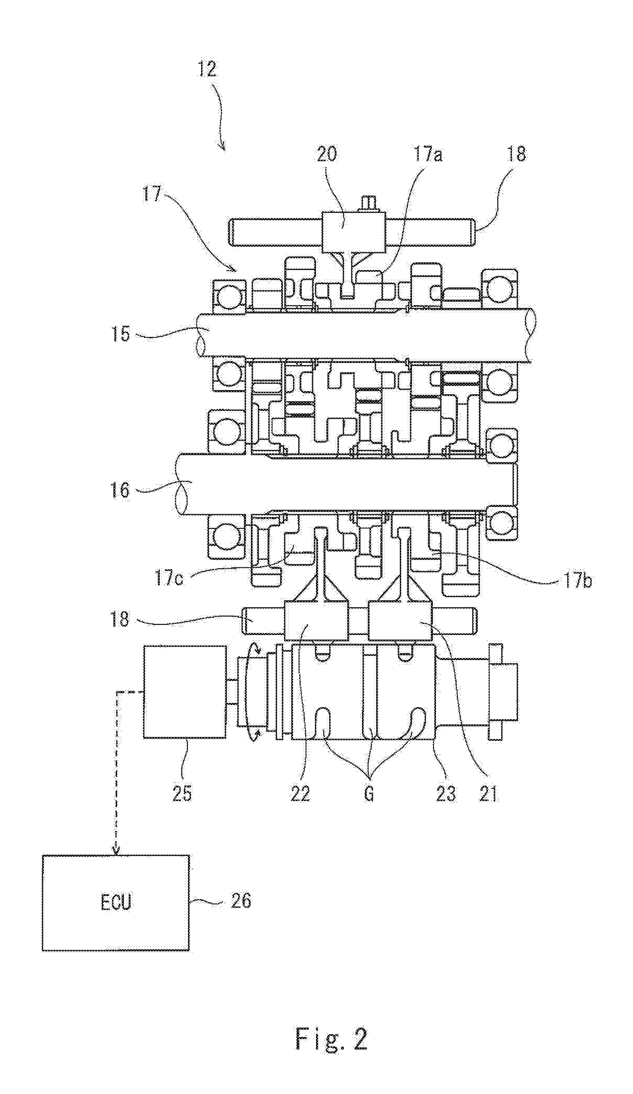
CROSS-REFERENCE TO THE RELATED APPLICATION[0001]This application claims priority to and the benefit of Japanese Patent Application No. 2017-175964 filed on Sep. 13, 2017, the entire disclosure of which is incorporated herein by reference.BACKGROUND OF THE INVENTIONField of the Invention[0002]The present invention relates to a straddle vehicle including a gear position sensor which detects a rotation angle of a shift drum.Description of Related Art[0003]Japanese Laid-Open Patent Application Publication No. 2012-197853 discloses that an engagement groove is formed in an axial end surface of a shift drum which changes a transmission gear position of a transmission, an engagement pin of the gear position sensor inserted into an insertion hole of a crankcase (transmission case) is engaged with the engagement groove, and thus a rotation angle of the shift drum is detected.[0004]In a case where an operator performs work for inserting a gear position sensor into an insertion hole of a crank...

Claims


Application Information

Patent Timeline
IPC IPC(8): F16H57/00B62M25/00B62H1/00F16H63/08B62J99/00F16H59/70
CPCF16H57/00B62M25/00B62H1/00F16H63/08B62J99/00F16H59/70B62M2701/0007B62J2099/002F16H2057/0056B62M25/06F16H63/18F16H2057/02065B62J45/413B62J45/42
Inventor YAMAMOTO, TETSUJIINAGAKI, YOSHIHIKO
Owner KAWASAKI MOTORS LTD
Learn More