
Interior permanent magnet electric machine

a permanent magnet electric machine and permanent magnet technology, applied in the field of electric machines, can solve the problems of vibration and noise affecting the operation, and achieve the effect of reducing eddy loss and torque rippl

Inactive Publication Date: 2019-02-28
HIWIN MIKROSYST
View PDF1 Cites 0 Cited by
  • Summary
  • Abstract
  • Description
  • Claims
  • Application Information

AI Technical Summary

Benefits of technology

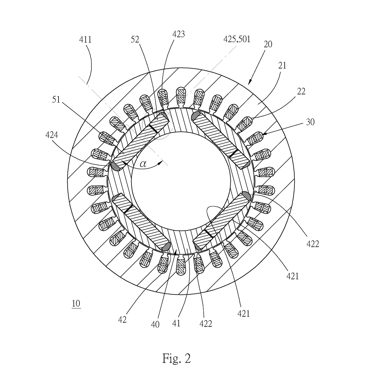
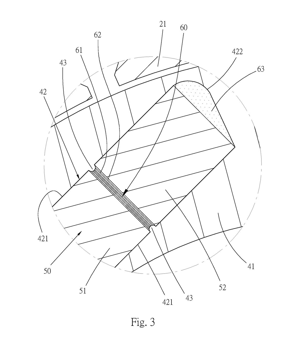
The present invention aims to offer an interior permanent magnet electric machine that can minimize the eddy loss and torque ripple. To achieve this, the rotor core has a radial axis, and each magnet unit includes a magnet axis. By aligning the radial axis with the magnet axis at an angle between 85° and 90°, the angle α increases the magnetic spread angle and the distribution of the magnets, resulting in a continuous magnetic field line between neighboring magnet units. This reduces torque ripple and improves the performance of the electric machine.

Problems solved by technology

Although the permanent magnet electric machine can enhance the efficiency by increasing the constant power speed range with the magnet control technology, the vibration and the noise will affect the operation thereof.

Method used


Image

  • Interior permanent magnet electric machine
  • Interior permanent magnet electric machine
  • Interior permanent magnet electric machine

Examples


Embodiment Construction

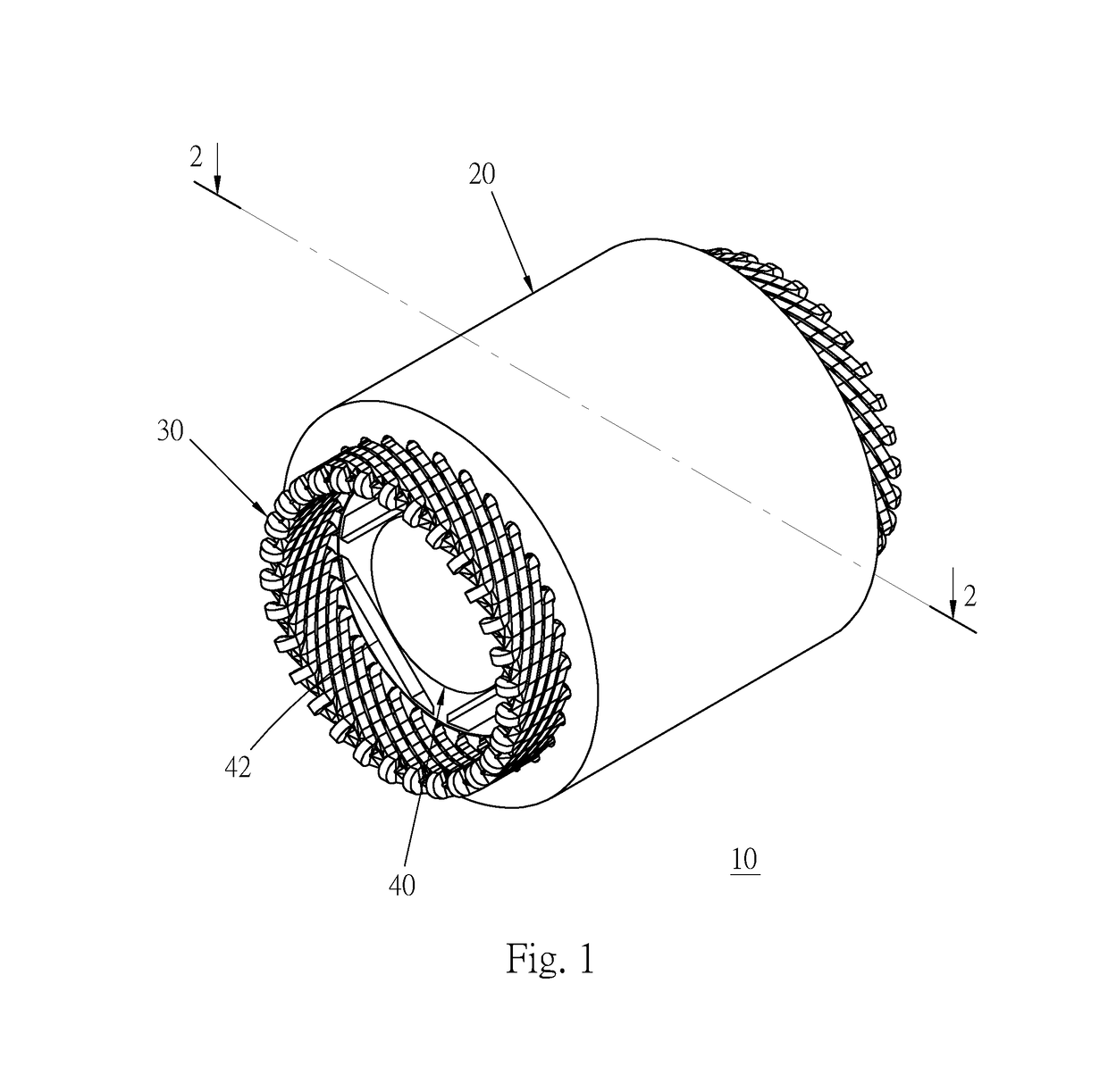
[0015]Refer to FIG. 1 to FIG. 3. The interior permanent magnet electric machine 10 includes a stator 20, a plurality of coils 30 and a rotor 40, a plurality of magnet units 50 and a plurality of divisions 60.

[0016]The stator 20 includes a circular stator core 21 and grooves 22 wherein the grooves 22 are configured on the inner circumference of the stator core 21 radially. The coils 30 are distributing winded within the grooves 22 respectively, but the coils 30 can be centralizing winded within the grooves 22 respectively in other embodiment. The technology of the stator 20 and the coils 30 is mature prior art, so there is no more detailed description herein.

[0017]The rotor 40 includes a rotor core 41, a plurality of slots 42 and a plurality of protrusions 43. The rotor core 41 is configured by stacking a plurality of silicon steel sheets. The slots 42 are equally and respectively disposed on the rotor core 41 in the form of long and narrow holes. The protrusions 43 are symmetrically...


PUM


Abstract

An interior permanent magnet electric machine including a stator, a rotor, a plurality of magnet units and a plurality of divisions is provided. The magnet units are contained within the slots of the rotor. Each magnet unit includes at least two magnets, and the divisions are configured between the neighboring magnets to separate the magnets such that the magnetic distribution is enlarged and the torque ripple is decreased.

Description

BACKGROUND OF THE INVENTIONField of the Invention[0001]The invention relates to an electric machine, and more particularly to an interior permanent magnet electric machine.Description of the Related Art[0002]The spindle motor is generally applied to the machine tool, such as lathe or milling machine, to provide rotation for the workpiece or tool to perform various operations.[0003]Concerning to the tradeoff between the cost and the efficiency, the conventional machine tool usually takes the asynchronous electric machine as the spindle motor. With the development of the electric machine, the permanent magnet synchronous electric machine has gradually been substituted for the asynchronous electric machine as the spindle motor.[0004]Although the permanent magnet electric machine can enhance the efficiency by increasing the constant power speed range with the magnet control technology, the vibration and the noise will affect the operation thereof. With respect to the conventional techno...

Claims


Application Information

Patent Timeline
Patent Type & Authority Applications(United States)
IPC IPC(8): H02K1/27
CPCH02K1/276H02K1/2773H02K1/30H02K21/14H02K29/03
Inventor ZHANG, ZHE-WEIKUO, CHEN-NAN
Owner HIWIN MIKROSYST
Learn More