
Magnetic pole position detecting device for sycnronous motor and magnetic pole position detecting method for sycnronous motor

a magnetic pole position and motor technology, applied in the direction of electronic commutator control, electronic commutator, instruments, etc., can solve the problems of synchronous motors that cannot generate desired torque and go out of control, and achieve the effect of easy and accurate determination of abnormal magnetic pole position detection

Active Publication Date: 2019-02-07
FANUC LTD
View PDF4 Cites 0 Cited by
  • Summary
  • Abstract
  • Description
  • Claims
  • Application Information

AI Technical Summary

Benefits of technology

The present invention makes it easy to find out if there is a problem with detecting the position of magnetic poles caused by the detector being placed in the wrong position.

Problems solved by technology

However, when the mounting position of the rotational position detector shifts due to deterioration over time, or when the mounting position deviates at the time of attaching the rotational position detector, there is a risk that the synchronous motor becomes unable to generate a desired torque and goes out of control.

Method used


Image

  • Magnetic pole position detecting device for sycnronous motor and magnetic pole position detecting method for sycnronous motor
  • Magnetic pole position detecting device for sycnronous motor and magnetic pole position detecting method for sycnronous motor

Examples


first embodiment

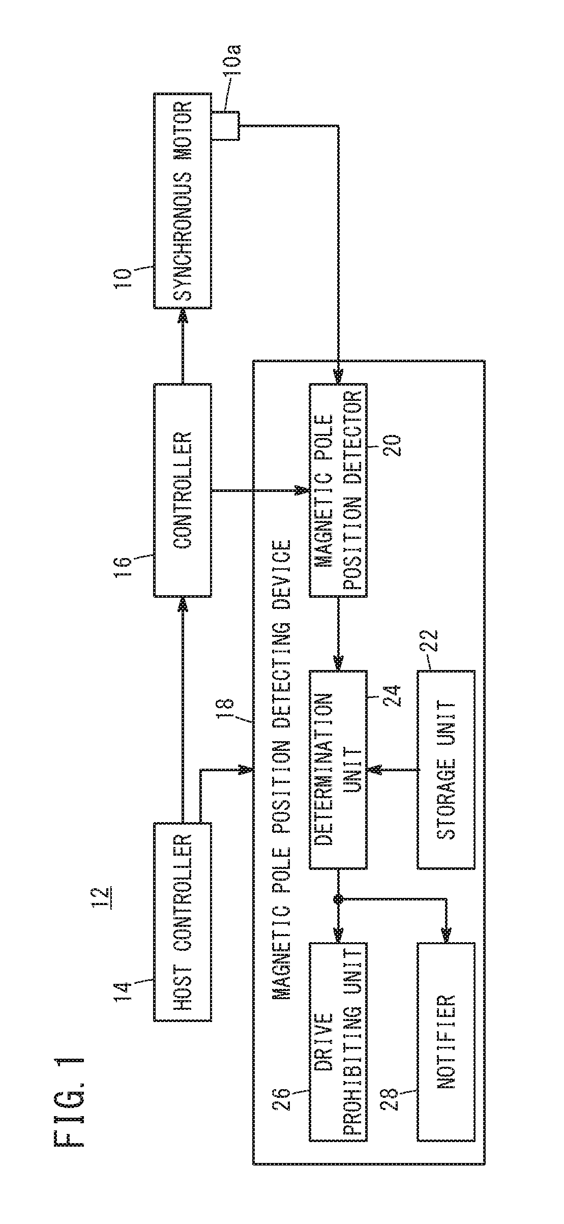
[0014]FIG. 1 is an electrical configuration diagram of a control system 12 having a synchronous motor 10. The control system 12 includes a synchronous motor 10, a host controller 14, a controller (motor controller) 16 and a magnetic pole position detecting device 18.

[0015]The synchronous motor 10 is a servomotor attached to a machine tool, a robot or the like. The synchronous motor 10 is provided with a position detector (e.g., encoder) 10a that detects the rotational position of the synchronous motor 10 (more specifically, the rotational position of the rotor of the synchronous motor 10). The rotational speed of the synchronous motor 10 (more specifically, the rotational speed of the rotor of the synchronous motor 10) is also known by detection of the rotational position from the position detector 10a.

[0016]The host controller 14 controls the controller 16 and outputs a speed command or a position command to the controller 16 according to a program (for example, a machining progra...

modified examples

[0034]The above embodiment may be modified as follows.

modified example 1

[0035]In the above embodiment, the host controller 14 and the controller 16 are explained separately, but a single controller may be functioned as the host controller 14 and the controller 16.


PUM


Abstract

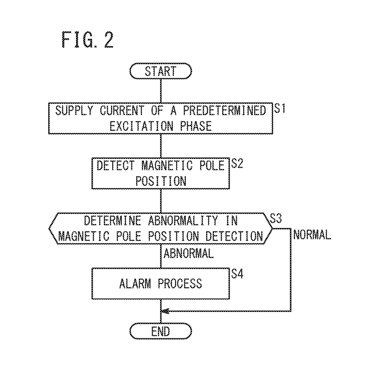
A magnetic pole position detecting device for a synchronous motor includes: a storage unit for storing a reference magnetic pole position of the synchronous motor as a predetermined reference; a magnetic pole position detector for detecting the magnetic pole position of the synchronous motor when a predetermined condition is satisfied; and a determination unit for comparing the reference magnetic pole position stored in the storage unit with the magnetic pole position detected by the magnetic pole position detector to determine that detection of the magnetic pole position is abnormal when the difference between the two falls out of a predetermined range.

Description

CROSS-REFERENCE TO RELATED APPLICATION[0001]This application is based upon and claims the benefit of priority from Japanese Patent Application No. 2017-152509 filed on Aug. 7, 2017, the contents of which are incorporated herein by reference.BACKGROUND OF THE INVENTIONField of the Invention[0002]The present invention relates to a magnetic pole position detecting device for a synchronous motor and a magnetic pole position detecting method for a synchronous motor to determine abnormality in magnetic pole position detection in a synchronous motor.Description of the Related Art[0003]In order for a synchronous motor to generate a desired torque, current having a phase corresponding to a magnetic pole position needs to be supplied to the synchronous motor. Therefore, to control the synchronous motor, it is necessary to accurately detect the magnetic pole position. The magnetic pole position is detected using a detection signal of a position detector such as an encoder attached to the synch...

Claims


Application Information

Patent Timeline
Patent Type & Authority Applications(United States)
IPC IPC(8): H02P6/18H02P6/12G07C5/08H02P25/022
CPCH02P6/181H02P6/12G07C5/0825H02P25/022H02P2203/03H02P6/16H02P2207/05H02P25/024
Inventor YAMAMOTO, KENTASONODA, NAOTO
Owner FANUC LTD
Learn More