
A device and method for determining the parallelism of the optical axis of a continuous zoom TV

A technology of parallelism and television, applied in the direction of testing optical performance, etc., can solve the problems of heavy repetitive workload, inability to use upper-level devices or product equipment, difficult adjustment, etc., and achieve the effect of high repeatability

Active Publication Date: 2017-01-11
西安应用光学研究所
View PDF1 Cites 0 Cited by
  • Summary
  • Abstract
  • Description
  • Claims
  • Application Information

AI Technical Summary

Problems solved by technology

[0006] 1. It can only be used to determine the optical axis of the zoom lens. There is no shape and position tolerance relationship between the zoom axis and the installation reference, and it cannot be directly used in the photoelectric stabilization device;
[0007] 2. During debugging, it is necessary to adjust the collimator so that the cross reticle does not move during the zooming process. In case of a large collimator, it is difficult to adjust, and the zoom lens and CCD need to search for images again, and the work is repeated during adjustment. large
[0008] The above methods and patents only determine the zoom axis of the continuous zoom optical system, and do not establish a spatial position relationship between this virtual zoom axis and any reference, and cannot be used in upper-level devices or product equipment

Method used


Image

  • A device and method for determining the parallelism of the optical axis of a continuous zoom TV
  • A device and method for determining the parallelism of the optical axis of a continuous zoom TV
  • A device and method for determining the parallelism of the optical axis of a continuous zoom TV

Examples


Embodiment Construction

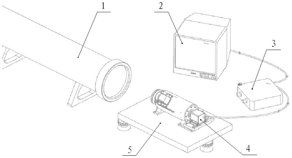
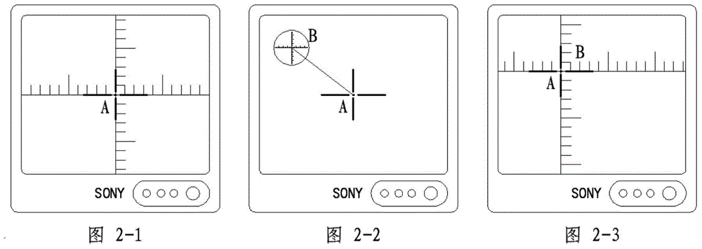
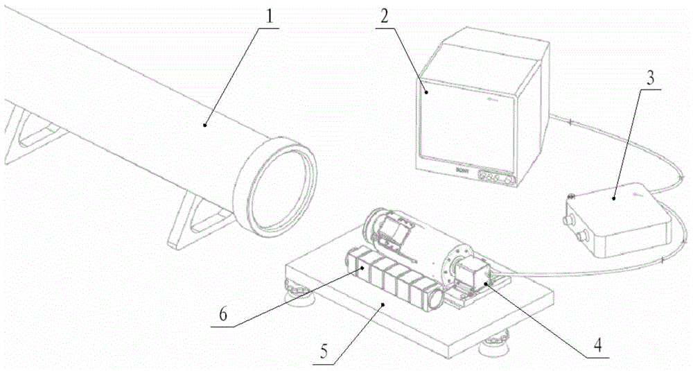
[0029] The present invention will be described in further detail below in conjunction with the accompanying drawings and preferred examples.

[0030] The method for determining the parallelism of the optical axes of the continuous zoom TV in this embodiment includes: a collimator 1 , a display 2 , an electric cross generator 3 , an adjustable platform 5 and a square tube front mirror 6 .

[0031] The collimator 1 provides parallel light with a cross reticle; the display 2 is a full-field display capable of displaying the cross reticle image received by the continuous zoom TV 4 and the electric cross image of the continuous zoom TV 4; The cross generator 3 can calibrate the coordinate position of the zoom axis on the display; the adjustable platform 5 is used to place the continuous zoom TV 4 and the square tube front mirror 6, and can adjust the spatial position at the same time; the square tube front mirror 6 serves as a continuous zoom The reference datum of the TV 4 is plac...


PUM


Abstract

The invention provides a device and a method for determining parallelism of a continuous zooming television optical axis. The determining method of the optical axis includes: placing a continuous zooming television on an adjustable platform, and aligning with a parallel optical pipe with a cross division; connecting an eclectic cross generator and a display at the same time; due to that when the television zooms, a cross division image on the display generates approximately linear displacement, adjusting relative position of the zooming television to ensure that the cross division image on the display is immovable when the television zooms, at the moment the optical axis of the parallel optical pipe being the optical axis of the continuous zooming lens; further adjusting space position of the zooming television CCD, thus ensuring that the zooming axis is accordant with the center position of the target surface of CCD. Deviation between the cross partition of the parallel optical pipe and the electric cross partition of the zooming television can be observed on the display through aligning the preset lens of a square pipe with the cross partition of the parallel optical pipe and placing the same tightly adjacent to the side reference of the zooming television, and the deviation can be eliminated by two reference surface of the zooming television, namely ensuring the parallelism of the zooming axis and the optical axis of the installing base plane.

Description

technical field [0001] The invention belongs to the technical field of optical adjustment, and specifically relates to a device and a determination method for determining the parallelism of optical axes of a continuous zoom television. Background technique [0002] During the optical-mechanical assembly process of the continuous zoom optical system, it is necessary to adjust the center of the image sensor to the optical axis of the continuous zoom lens. If the continuous zoom lens has no reference plane, or the reference plane is not accurate, it is necessary to determine the The optical axis of the lens, and then the center of the image sensor can be adjusted to the optical axis of the continuous zoom lens. [0003] At present, there are many ways to determine the zoom axis of the continuous zoom optical system. For the continuous zoom lens with a reference plane, it is usually the end face of the lens barrel. The method of determining the optical axis is relatively simple....

Claims


Application Information

Patent Timeline
Patent Type & Authority Patents(China)
IPC IPC(8): G01M11/02
Inventor 刘欣张锦亮惠刚阳闫伟亮张伟平张燕王章利左小舟王中强
Owner 西安应用光学研究所
Learn More