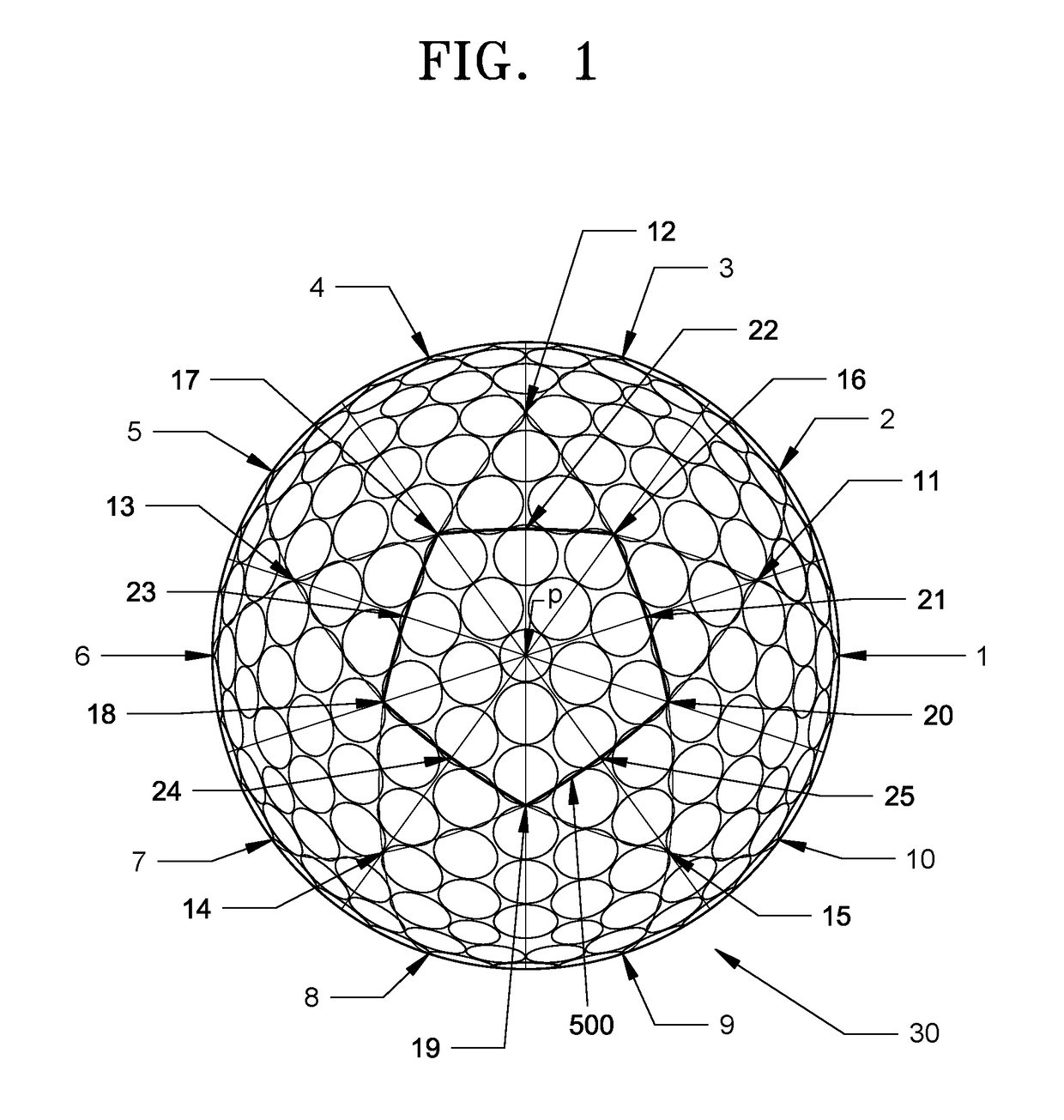
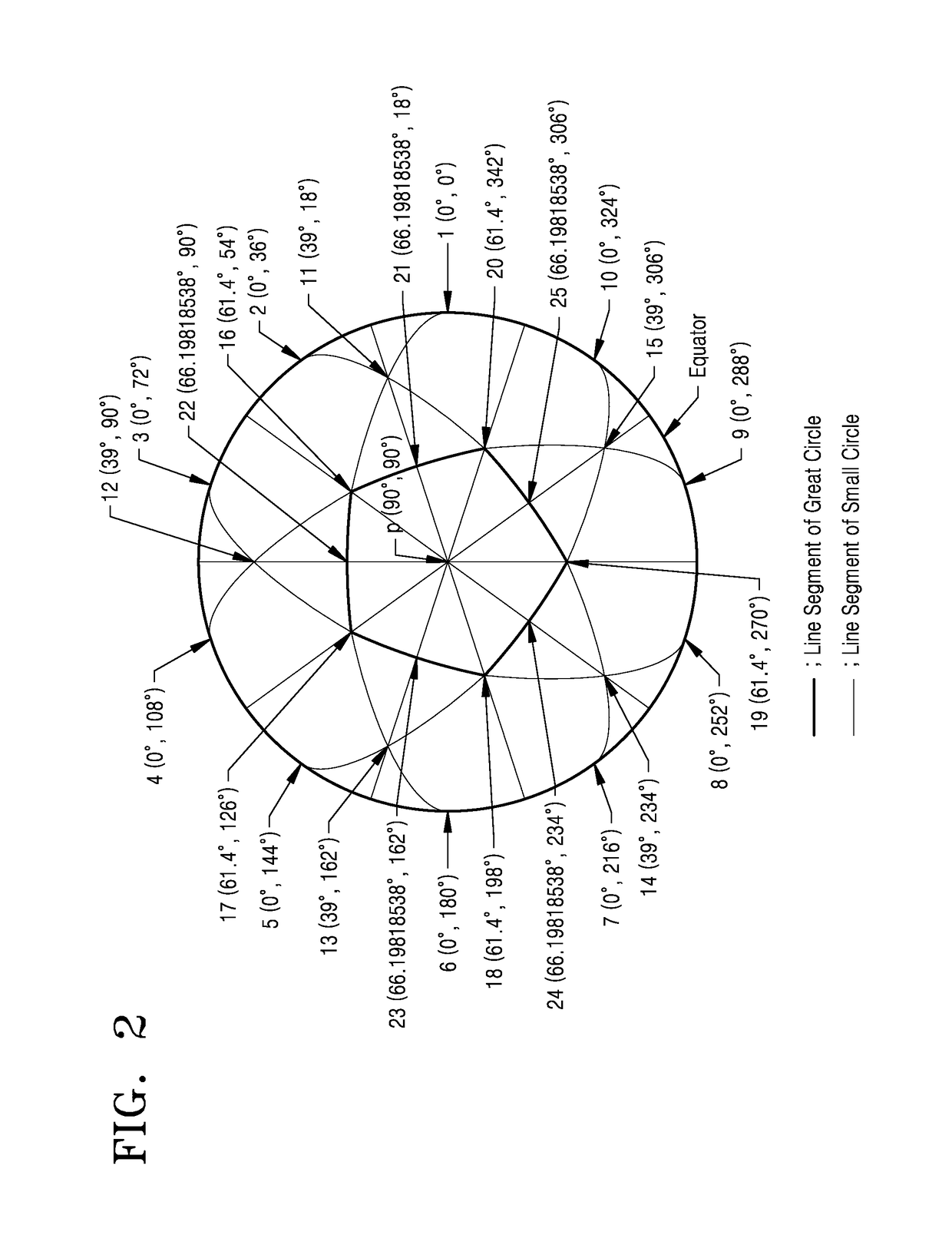
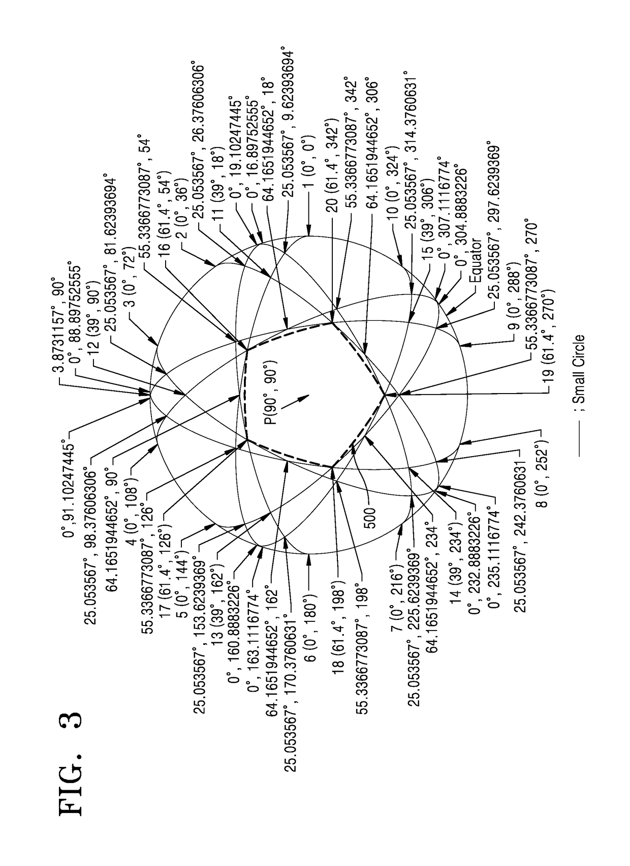
Golf ball having surface divided by line segments of great circles and small circles
a golf ball and line segment technology, applied in the field of golf balls, can solve the problems of difficult to obtain lift force, limit in improving the dimple area ratio, and negatively affecting the lift force of golf balls manufactured as abov
- Summary
- Abstract
- Description
- Claims
- Application Information
AI Technical Summary
Benefits of technology
Problems solved by technology
Method used
Image

Examples
Embodiment Construction
[0025]Reference will now be made in detail to embodiments, examples of which are illustrated in the accompanying drawings, wherein like reference numerals refer to like elements throughout. In this regard, the present embodiments may have different forms and should not be construed as being limited to the descriptions set forth herein. Accordingly, the embodiments are merely described below, by referring to the figures, to explain aspects of the present description.
[0026]A surface dividing method while maintaining symmetry has been researched in various ways. In general, when a surface is divided by a plurality of great circles, symmetry may be maintained with no problem. In this case, however, when dimples having substantially the same size only are arranged in spherical polygons, a sufficient dimple area ratio may not be obtained, or even when a sufficient dimple area ratio is obtained by using dimples of various sizes, manufacturing a mold for such a golf ball having dimples of v...
PUM
 Abstract
Description
Claims
Application Information
 - R&D
- Intellectual Property
- Life Sciences
- Materials
- Tech Scout
- Unparalleled Data Quality
- Higher Quality Content
- 60% Fewer Hallucinations
Browse by: Latest US Patents, China's latest patents, Technical Efficacy Thesaurus, Application Domain, Technology Topic, Popular Technical Reports.
© 2025 PatSnap. All rights reserved.Legal|Privacy policy|Modern Slavery Act Transparency Statement|Sitemap|About US| Contact US: help@patsnap.com