
Method and apparatus for combining data to construct a floor plan

a technology of floor plans and depth data, applied in the field of floor plans, can solve the problems of large amount of memory required for data collection, large computational power required to process a large number of features, and inability to meet the needs of users,

Active Publication Date: 2019-01-31
AI INC
View PDF12 Cites 42 Cited by
  • Summary
  • Abstract
  • Description
  • Claims
  • Application Information

AI Technical Summary

Benefits of technology

The patent describes a process for analyzing images taken from different positions using a robot. The process includes aligning image values based on sensor readings and inferring features of the robot's working environment. The technical effect is a more accurate and reliable method for analyzing image data and obtaining information about the robot's environment.

Problems solved by technology

The main drawback of using an EKF approach is the computational power required to process a large number of features having large total state vector and covariance matrix.
The computational delays may limit the speed of robot movement and task performance.
Additionally, the data collected in creating and updating the map requires large amounts of memory.
Another issue with EKF SLAM approach is data association due to the presence of similar features in the map whereby different data association hypotheses can result in multiple distinct maps.
While several data association algorithms have been developed to solve this issue, they cannot be implemented in real-time with commercially reasonable amounts of computing resources.
Another issue with EKF-based SLAM approach, is the performance of the SLAM often highly depends on the accuracy of measurement noise covariance matrices, both of which are typically required a priori.
Incorrect knowledge of sensor statistics can lead to degradation in performance.
Furthermore, this type of SLAM method employs sophisticated techniques, often requiring considerable costs for implementation.
For example, U.S. Pat. No. 5,896,488 describes a method to map the environment using ultrasonic sensors wherein the robotic device follows along the walls while measuring distance and tracking movement to map the perimeter of the environment, however this method prevents the robotic device from performing work away from the perimeters while simultaneously mapping.
This method is limited as the robotic device must complete a 360-degree rotation to map the area before beginning any coverage.

Method used


Image

  • Method and apparatus for combining data to construct a floor plan
  • Method and apparatus for combining data to construct a floor plan
  • Method and apparatus for combining data to construct a floor plan

Examples


Embodiment Construction

[0031]The present inventions will now be described in detail with reference to a few embodiments thereof as illustrated in the accompanying drawings. In the following description, numerous specific details are set forth in order to provide a thorough understanding of the present inventions. It will be apparent, however, to one skilled in the art, that the present inventions, or subsets thereof, may be practiced without some or all of these specific details. In other instances, well known process steps and / or structures have not been described in detail in order to not unnecessarily obscure the present inventions. Further, it should be emphasized that several inventive techniques are described, and embodiments are not limited to systems implanting all of those techniques, as various cost and engineering trade-offs may warrant systems that only afford a subset of the benefits described herein or that will be apparent to one of ordinary skill in the art.

[0032]Some of the embodiments in...


PUM


Abstract

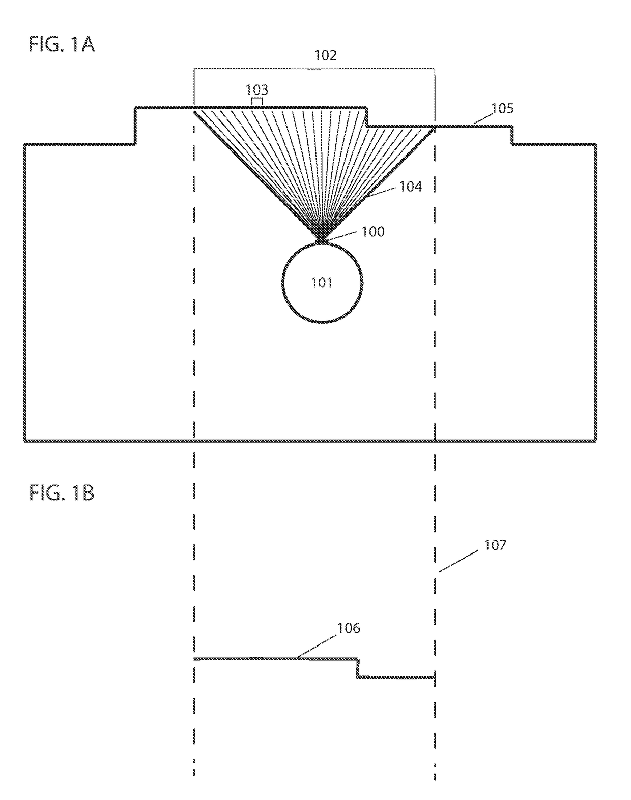
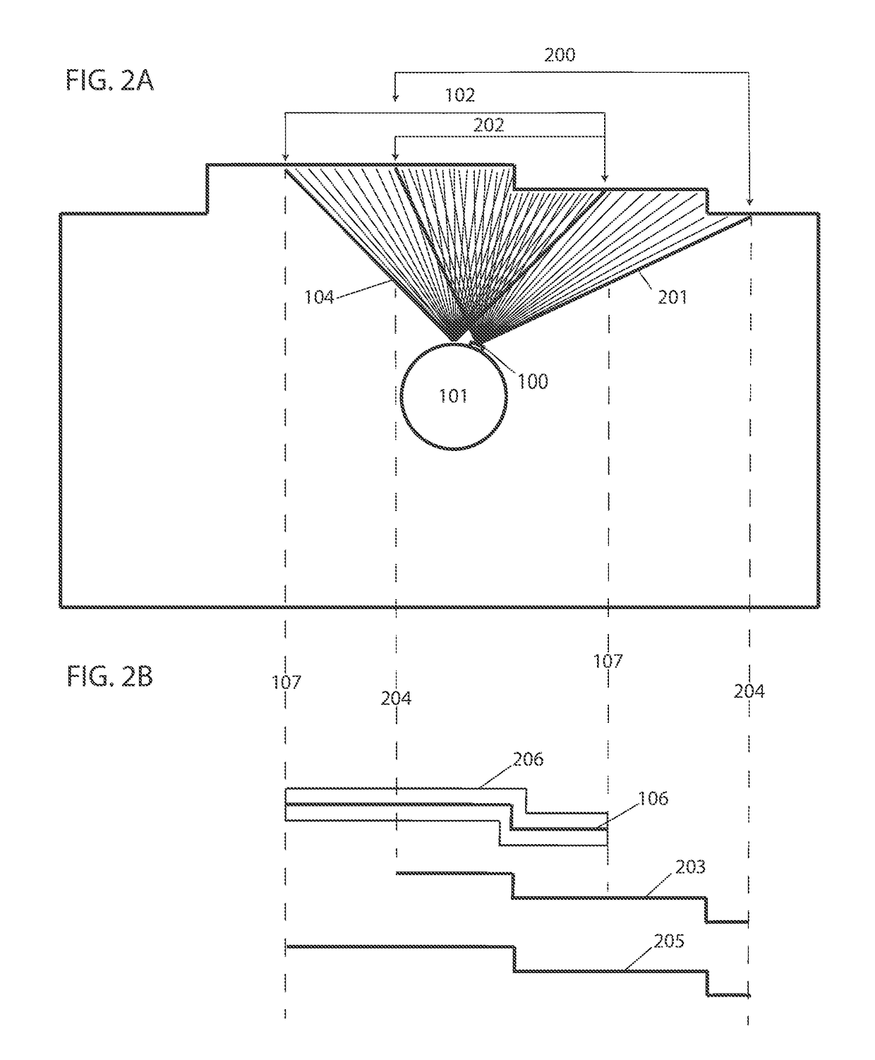
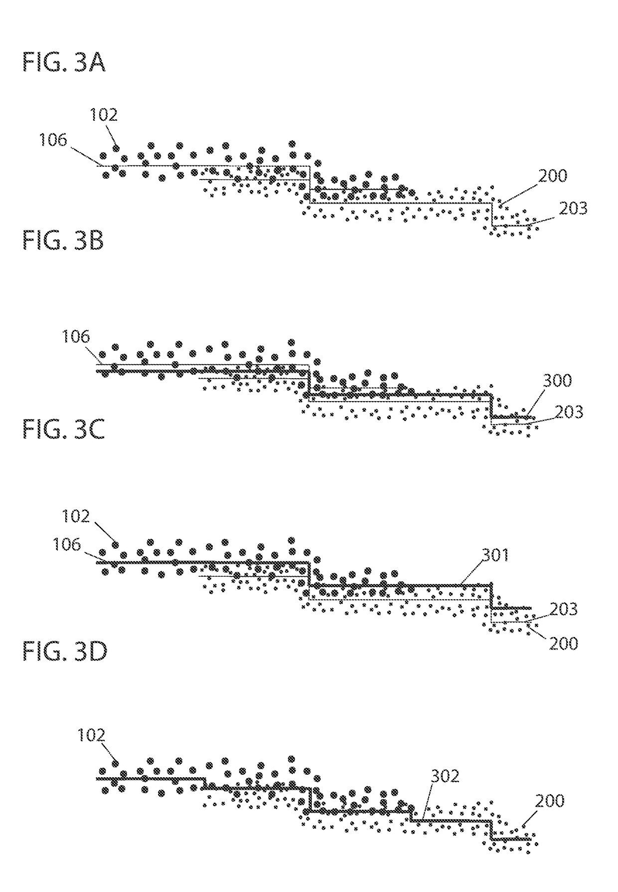
Provided is a process, including obtaining, with a robot, raw pixel intensity values of a first image and raw pixel intensity values of a second image, wherein the first image and the second image are taken from different positions; determining, with one or more processors, an overlapping area of a field of view of the first image and of a field of view of the second image by comparing the raw pixel intensity values of the first image to the raw pixel intensity values of the second image; spatially, with one or more processors, aligning values based on sensor readings of the robot based on the overlapping area; and inferring, with one or more processors, features of a working environment of the robot based on the spatially aligned sensor readings.

Description

CROSS-REFERENCE TO RELATED APPLICATIONS[0001]This application claims the benefit of Provisional Patent Application No. 62 / 537,858, filed Jul. 27, 2017, and claims the benefit of U.S. Provisional Patent Application No. 62 / 618,964, filed Jan. 18, 2018, and U.S. Provisional Patent Application No. 62 / 591,219, filed Nov. 28, 2017, each of which is hereby incorporated by reference. In this application, certain U.S. patents, U.S. patent applications, or other materials (e.g., articles) have been incorporated by reference. Specifically, in addition to the preceding, U.S. patent application Ser. Nos. 15 / 243,783, 62 / 208,791, 15 / 224,442, and 15 / 674,310 are hereby incorporated by reference. The text of such U.S. patents, U.S. patent applications, and other materials is, however, only incorporated by reference to the extent that no conflict exists between such material and the statements and drawings set forth herein. In the event of such conflict, the text of the present document governs, and t...

Claims


Application Information

Patent Timeline
IPC IPC(8): G06T7/593G01S17/89G06K9/00G06N5/04G06K9/62G06T7/30G06T7/13G01S7/48G06K9/20G01S17/86
CPCG06T7/593G01S17/89G06K9/00664G06N5/047G06K9/6202G06T7/30G06T7/13G01S7/4804G06K9/20G06T2207/10028G06K2009/2045G05D1/0253G05D1/0274G01S17/48G06N3/008G01S17/86G06V20/64G06V20/10G06V10/16G06V10/751G06N3/045G05D1/0227G01C21/32G06T7/73G06T17/05Y10S901/47G06V20/58G06T7/344G06T7/0002
Inventor EBRAHIMI AFROUZI, ALISCHWEIGERT, SEBASTIANZHANG, CHEN
Owner AI INC
Learn More