
Extensible lamp to reduce shadow

a technology of shadow reduction and extension lamp, which is applied in the direction of lighting support device, fixed installation, lighting and heating apparatus, etc., can solve the problems of requiring more space and/or aesthetic unpleasant, and achieve the effect of increasing the effective area of light emission, reducing shadows, and overall dimensions of lighting devices

Active Publication Date: 2019-01-31
LEDVANCE GMBH
View PDF1 Cites 2 Cited by
  • Summary
  • Abstract
  • Description
  • Claims
  • Application Information

AI Technical Summary

Benefits of technology

This patent is about a lighting device that reduces shadows and has a compact design. The device has a primary lighting module and a secondary lighting module that can be separated by a distance. When the device is expanded, it illuminates a wider area, reducing shadows caused by a person's hand or tool. The effective area of lighting in the expanded state is at least twice, preferably at least five times, the size of the collapsed state. The shapes of the modules are designed so there are no gaps between them in the collapsed state, and the device can achieve a high illumination intensity in this state.

Problems solved by technology

While lighting devices having a larger area of light emission exist, they usually require more space and / or are aesthetically unpleasing, especially when not in use.

Method used


Image

  • Extensible lamp to reduce shadow
  • Extensible lamp to reduce shadow
  • Extensible lamp to reduce shadow

Examples


Embodiment Construction

[0033]In the following, preferred embodiments of the invention will be described with reference to the drawings. The same or similar elements or elements having the same effect may be indicated by the same reference number in multiple drawings. Repeating the description of such elements may be omitted in order to prevent redundant descriptions.

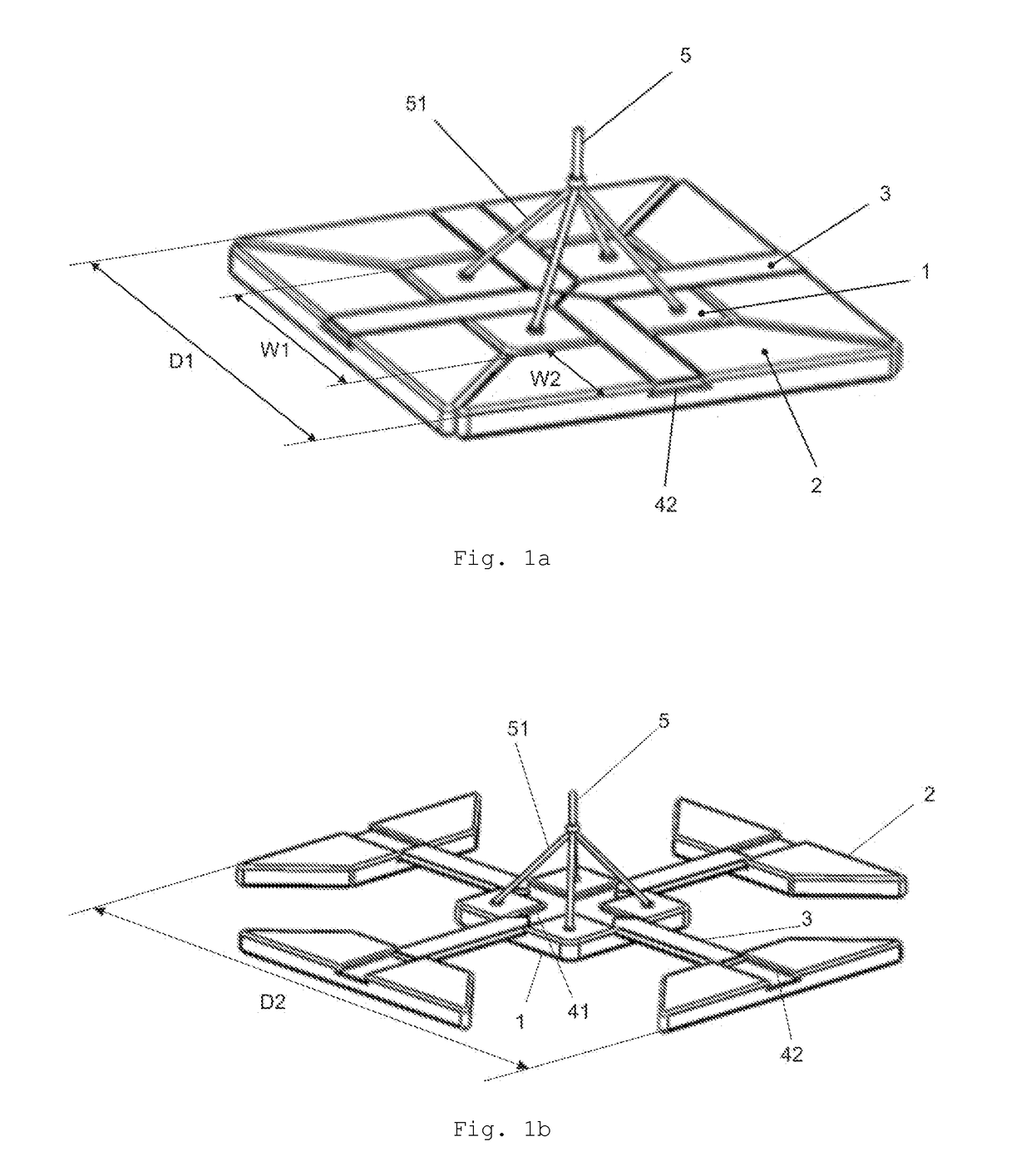
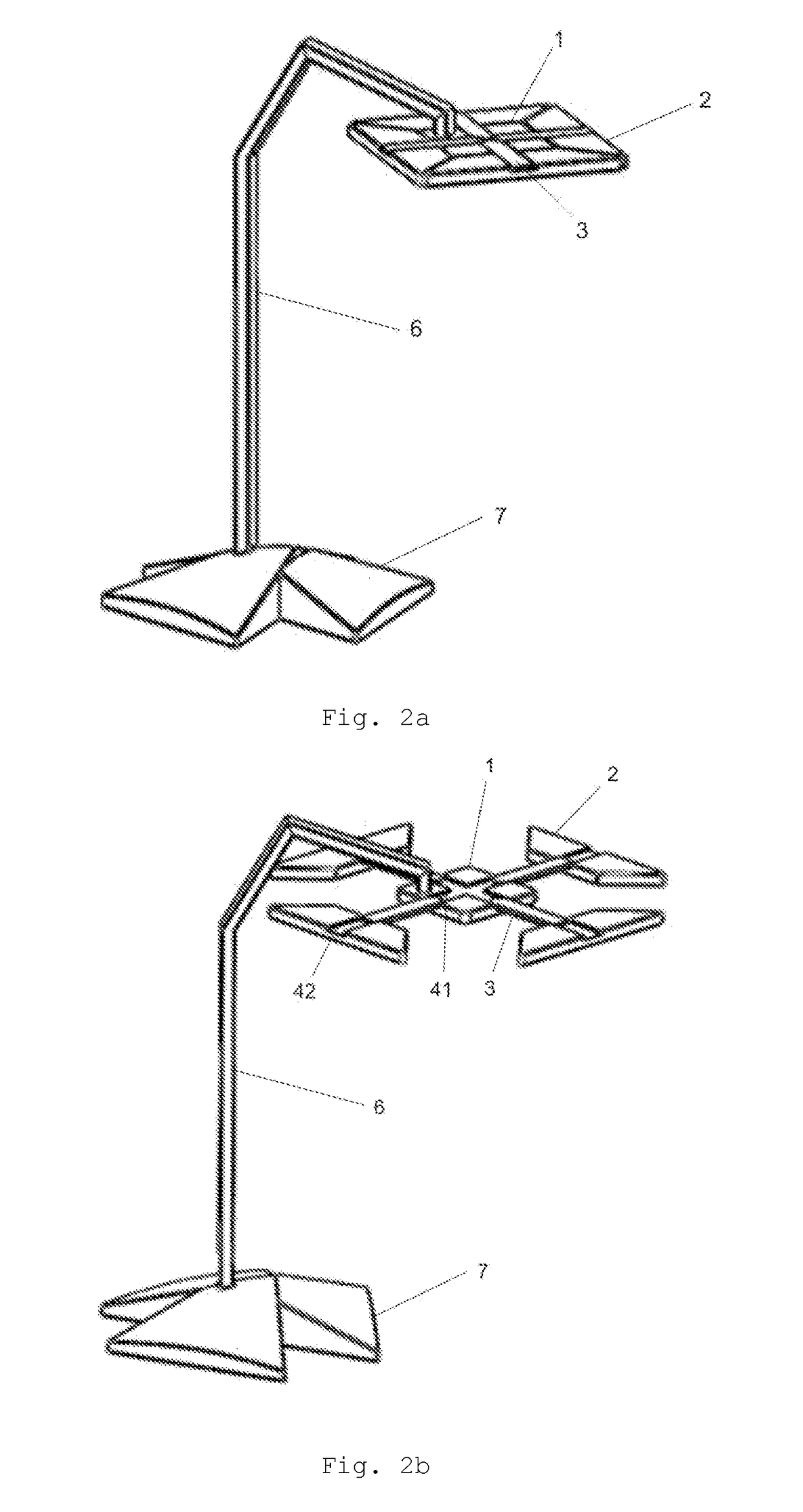
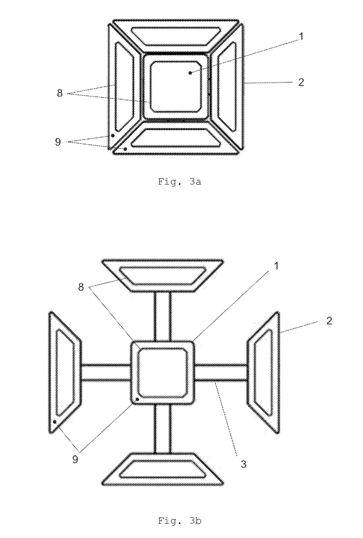
[0034]FIG. 1a shows an embodiment of a ceiling lamp having a variable shape according to the present invention in a collapsed state. FIG. 1b shows the ceiling lamp of FIG. 1a in an expanded state.

[0035]The ceiling lamp comprises a primary lighting module 1 and four secondary lighting modules 2. The perspective view of FIGS. 1a and 1b shows the upper side of the lighting modules 1, 2. Each lighting module 1, 2 comprises multiple light emitting diodes (LEDs, not shown) on its lower side. The LEDs may be provided on a PCB (not shown) and may be covered by a diffusing cover (not shown in FIGS. 1a, 1b) in order to achieve smooth illumination.

[0036]...


PUM


Abstract

A lighting device includes a primary lighting module with one or more light sources and one or more secondary lighting modules each with one or more light sources. Each secondary lighting module is mechanically and electrically connected to the primary lighting module. At least one of the secondary lighting modules is movable with respect to the primary lighting module. The shape of the lighting device can be varied between a collapsed state requiring less space and an expanded state for the reduction of shadows.

Description

CROSS-REFERENCE TO RELATED APPLICATIONS AND PRIORITY[0001]This patent application claims priority from Chinese Patent Application No. 2017106191665 filed Jul. 26, 2017, which is herein incorporated by reference in its entirety.TECHNICAL FIELD[0002]The present invention relates to a lighting device having a variable shape.BACKGROUND[0003]Currently, many lighting devices, for example table lamps or ceiling lamps, have a rather small area of light emission. In particular when used for illuminating a working area, such as a writing desk, shadows generated by hands, tools, etc. located between the lighting device and the working area are very dark as compared to the otherwise illuminated region.[0004]While lighting devices having a larger area of light emission exist, they usually require more space and / or are aesthetically unpleasing, especially when not in use.SUMMARY OF THE INVENTION[0005]In view of the known prior art, it is an object of the present invention to provide a lighting de...

Claims


Application Information

Patent Timeline
Patent Type & Authority Applications(United States)
IPC IPC(8): F21V14/02F21V19/00F21K9/20F21S6/00F21S8/06
CPCF21V14/02F21V19/0045F21K9/20F21S6/003F21S8/06F21V21/35F21Y2115/10F21V21/34F21V23/004F21S8/061
Inventor LIN, JING
Owner LEDVANCE GMBH
Learn More