Eureka AIR delivers breakthrough ideas for toughest innovation challenges, trusted by R&D personnel around the world.

Pilot type switching valve

a technology of switching valve and pilot type, which is applied in the direction of valve housing, functional valve type, servomotor, etc., can solve the problem of increasing the size of the pilot type switching valve, and achieve the effect of suppressing the size increas

Active Publication Date: 2019-01-24
KYB CORP
View PDF9 Cites 0 Cited by
  • Summary
  • Abstract
  • Description
  • Claims
  • Application Information

AI Technical Summary

Benefits of technology

The purpose of this patent is to create a pilot type switching valve that can control the flow of a fluid while keeping the size of the valve small.

Problems solved by technology

Thus, there is a risk that the size of the pilot type switching valve is increased.

Method used


Image

  • Pilot type switching valve
  • Pilot type switching valve
  • Pilot type switching valve

Examples


first embodiment

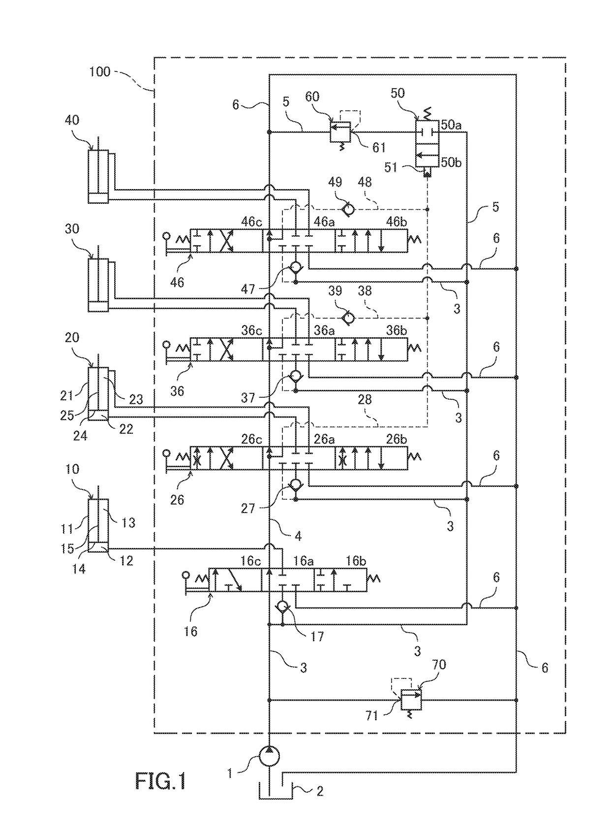
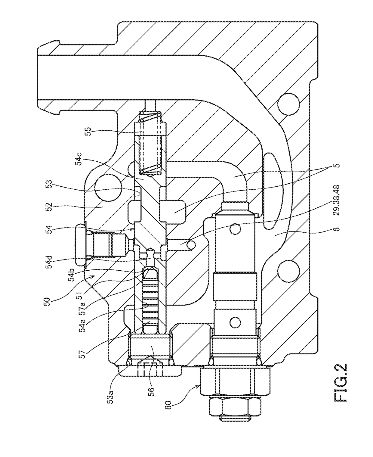
[0011]Hereinafter, a pilot type switching valve 50 according to a first embodiment of the present invention will be described with reference to the drawings. An example where a pilot type switching valve 50 is applied to a fluid pressure control device 100 to be mounted on a forklift will be described below. However, the present invention can also be applied to various devices other than the forklift.

[0012]Firstly, with reference to FIG. 1, the fluid pressure control device 100 to which the pilot type switching valve 50 is applied will be described.

[0013]The fluid pressure control device 100 controls work of a lift cylinder 10 that lifts and lowers a fork, a tilt cylinder 20 that changes an inclination angle of a mast, and attached equipment actuators 30, 40 that move other attached equipment. The other attached equipment includes a fork positioner that adjusts intervals of the fork.

[0014]Pressure upper limit values are respectively set for the lift cylinder 10, the tilt cylinder 20...

second embodiment

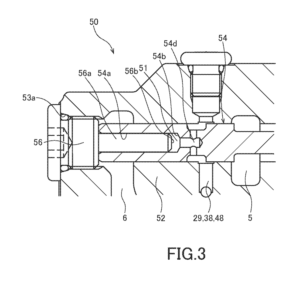
[0071]With reference to FIG. 4, a pilot type switching valve 150 according to a second embodiment of the present invention will be described. Hereinafter, points different from the above first embodiment will be mainly described, and the same configurations as the pilot type switching valve of the first embodiment will be given the same reference signs and description thereof will be omitted.

[0072]FIG. 4 is a partially enlarged view of the vicinity of a pilot chamber 151. The second embodiment shown in FIG. 4 is different from the first embodiment in a point that the pilot chamber 151 is provided in a recessed portion 156a formed in a plug 156. Specific description will be given below.

[0073]A spool 154 includes a main body portion 154a configured to slide on a housing bore 53, and a projecting portion 154b formed to project from an end surface of the main body portion 154a, the projecting portion having the smaller diameter than the diameter of the main body portion 154a. The main b...


PUM


Abstract

A pilot type switching valve includes: a housing bore formed in a valve body, the housing bore having an opening end; a spool slidably housed in the housing bore, the spool being configured to allow or block a flow of the working fluid to a first relief valve; a pilot chamber to which pilot pressure biasing the spool in the valve opening direction is guided; and a spring configured to bias the spool in the valve closing direction. The spool has a bottom surface on which the pilot pressure acts in such a manner that the spool is biased in the valve opening direction, and the area of the bottom surface is smaller than the sectional area of the housing bore.

Description

TECHNICAL FIELD[0001]The present invention relates to a pilot type switching valve.BACKGROUND ART[0002]JP01-102131A describes a hydraulic circuit in which a relief valve is provided on a flow passage branching from a flow passage which provides communication between a hydraulic pump and an assembled switching valve via a hydraulic pilot type switching valve.SUMMARY OF INVENTION[0003]In this type of hydraulic circuit, a valve having a structure in which a pilot chamber is provided on one end surface of a valve element formed in a cylindrical shape and a bias spring is provided on the other end surface is used as a pilot type switching valve.[0004]In the hydraulic circuit described in JP01-102131A, in order to ensure a relief flow rate of the relief valve, there is a need for increasing a flow rate of the hydraulic pilot type switching valve. When the flow rate is ensured by using the pilot type switching valve having the above structure, the diameter of the valve element is required ...

Claims


Application Information

Patent Timeline
Patent Type & Authority Applications(United States)
IPC IPC(8): F16K17/02F16K3/26
CPCF16K17/02F16K3/26F15B13/024F15B11/028F15B13/042F15B2211/50518F15B2211/511F15B2211/528F15B2211/56F15B2211/5756F15B2211/7142F15B2211/78F15B2211/30525F16K27/04F15B11/00
Inventor TERAO, TAKESHI
Owner KYB CORP
Why Eureka
Eureka Blog
Learn More