
Method And System For Designing A Biomechanical Interface Contacting A Biological Body Segment

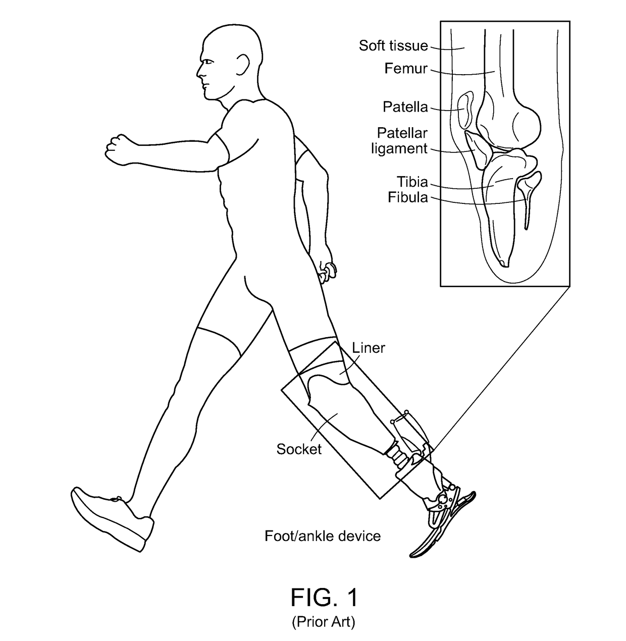
a biomechanical interface and biomechanical technology, applied in the direction of prosthesis, instruments, artificial legs, etc., can solve the problems of complex interface optimization, inability to strongly repeat, and largely non-data driven, so as to ensure user physiological benefits, avoid soft tissue injury, and accurately evaluate the deformation and loading conditions of soft tissue.

Pending Publication Date: 2019-01-24
MASSACHUSETTS INST OF TECH
View PDF0 Cites 12 Cited by
  • Summary
  • Abstract
  • Description
  • Claims
  • Application Information

AI Technical Summary

Benefits of technology

The invention offers a method and system for designing and evaluating prosthetic sockets using data-driven and automated tools. This approach reduces subject participation and improves repeatability and geometric fidelity. The system takes into account the shape and impedance of the prosthetic socket, allowing for virtual iteration and design optimization. The method also involves accurately recording tissue geometries, analyzing tissue behavior, and predicting the equilibrium shape of the socket and liner system. This allows for iterative design evaluation and reduces the need for user involvement. The technology can be applied to a range of wearable devices and body segments of humans and non-humans.

Problems solved by technology

As such, the optimization of the interface is complex as it consists of the determination of the appropriate interface geometry and mechanical properties given the geometry and mechanical properties of the local tissue for which the device is designed to interface.
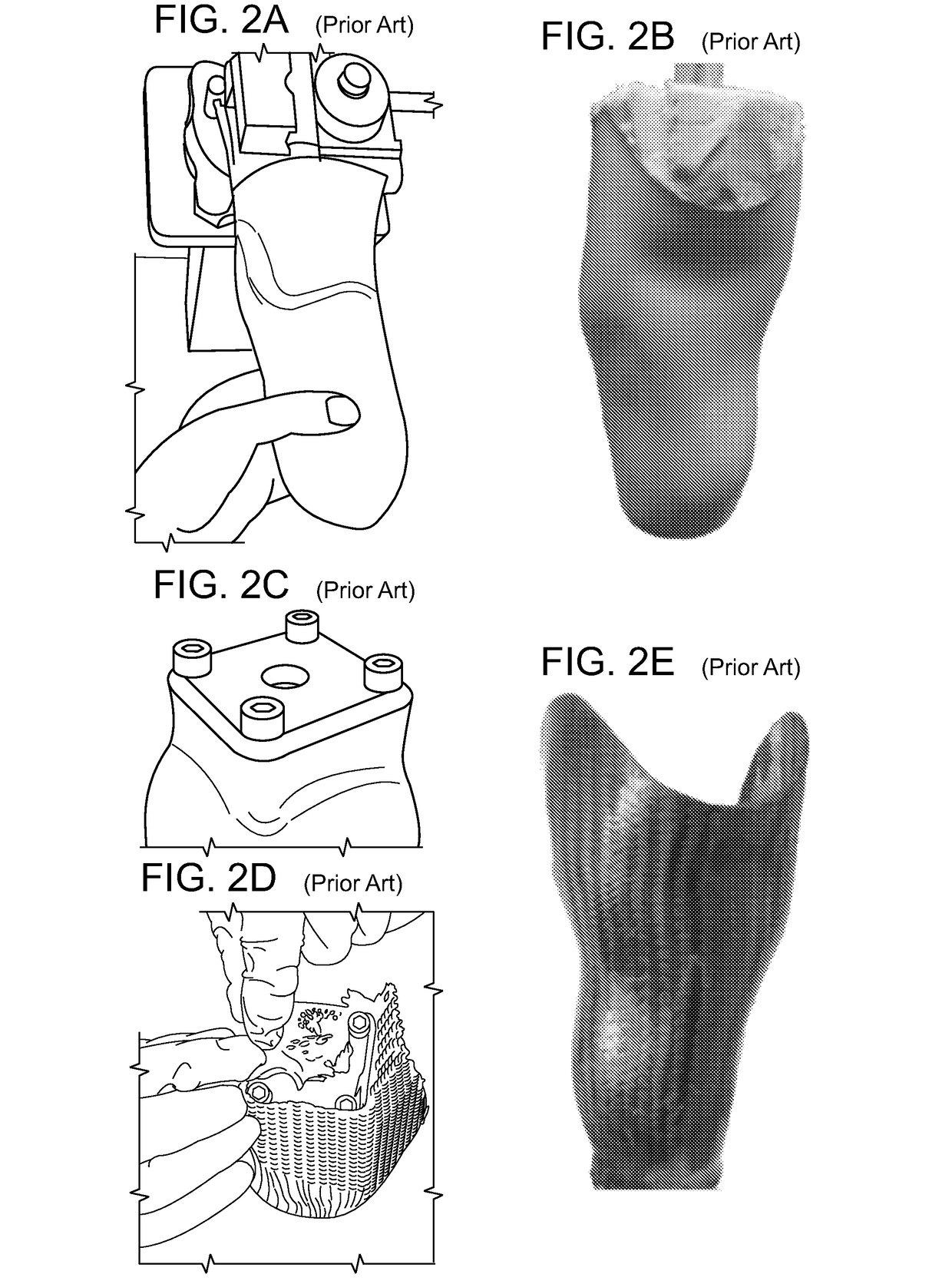
The manual nature of the process means it is not strongly repeatable and currently largely non-data-driven, and quantitative data is either not obtained or insufficiently employed.
As such there is a reported discrepancy in the quality of sockets produced by prosthetists [8].
Furthermore, it has been reported that 57% of lower extremity prosthetic users experience moderate to severe pain when wearing their device [9].
Discomfort commonly results in skin problems and tissue damage (e.g. [10]-[13]).
However, even mild discomfort may be concerning as it could result in an altered posture and gait, which in turn may cause long term musculoskeletal conditions such as back pain [17].
However, at present, these tools do not inform the design in a data-driven sense [28] since the actual design process remains a manual and experience based procedure.
This may explain the reported preferential indifference among subjects who used both a socket made using conventional and CAD / CAM techniques [29], and that design errors remain prevalent [30].
However, in all of these cases the soft tissue material behavior was modeled using linear elasticity which is not appropriate for analysis of large deformations.
In addition, linear elasticity does not consider deformation induced stiffness enhancement due to the non-linear elastic nature of soft tissue.
Since the equilibrium shapes of the liner and socket do not match the undeformed soft tissue they create significant pre-strain and pre-stress.
However, these displacements likely create unnatural deformations since in reality the materials may displace not only normal but also tangential to each other.
However, with this approach the tissue remains undeformed and stress and strain free which is not realistic.
However, contact simulations, combined with non-linear analysis, for such large relative motions are computationally intensive, especially if both the socket and tissue are deformable.
Hence there is no consensus as to what motion history to simulate for these donning simulations.

Method used


Image

  • Method And System For Designing A Biomechanical Interface Contacting A Biological Body Segment
  • Method And System For Designing A Biomechanical Interface Contacting A Biological Body Segment
  • Method And System For Designing A Biomechanical Interface Contacting A Biological Body Segment

Examples


Embodiment Construction

[0037]Despite advances in computer aided design technologies current design methodologies for biomechanical interfaces are not fully data-driven and are manual in nature, i.e. the design process may in some cases be computer aided, but has not been computer driven such that a computational system (rather than a human) performs the action of designing. Although some have used biophysical analysis (such as FEA) to evaluate loading of manually created designs, FEA (or a similar computational biophysical technique) has not been used for automated generation of designs, and has not been combined with automated iterative design evaluation and optimization. Further, current biophysical analyses have often considered soft tissue to be linear elastic and only relatively rigid socket materials have been employed. Finally, donning induced pre-loading of the biomechanical interface device and the soft tissue have not been incorporated in frameworks for design and design evaluation.

[0038]A need ...


PUM


Abstract

A method and associated system for designing a biomechanical interface of a device contacting a biological body segment of a subject includes forming a quantitative model of the biological body segment from subject specific data, conducting a biophysical analysis, such as a finite element analysis, to thereby establish a relationship, such as a functional relationship, between the quantitative model and at least one feature of the biomechanical interface contacting the biological body segment, and applying the relationship to the at least one feature of the biomechanical interface contacting the biological body segment to thereby obtain an interface design for the mechanical interface of the device. The subject-specific data can include geometry of the biological body segment and the at least one feature can be associated with physiological benefit of the biological body segment.

Description

RELATED APPLICATIONS[0001]This application claims the benefit of U.S. Provisional Application No. 62 / 278,158, filed on Jan. 13, 2016 and U.S. Provisional Application No. 62 / 377,128, filed on Aug. 19, 2016. The entire teachings of the above applications are incorporated herein by reference.BACKGROUND[0002]The success of technology such as ergonomic grips, form-fitting garments (e.g. shoes and bras), support structures (e.g. seating, wheelchair padding, mattresses, and cushions), wearable devices (e.g. glasses, hearing aids, watches), exoskeletons, orthopedic devices (orthopedic braces, bands and supports), and prosthetic devices (e.g. upper and lower limb prostheses), relies on the presence of a high-quality biomechanical interface. Typically, biomechanical interfaces achieve appropriate load transfer through artisanal modification of interface shape. In many cases the shape of the interface resembles that of the tissue region but may deviate from it, e.g., to provide a particular fi...

Claims


Application Information

Patent Timeline
IPC IPC(8): A61F2/50G06F17/50A61F2/80
CPCA61F2/5046G06F17/5009A61F2/80A61F2002/505A61F2002/607A61F2/78A61F2002/5049A61F2/60G06F30/23G06F30/20
Inventor HERR, HUGH M.MOERMAN, KEVIN MATTHEUSSENGEH, DAVID MOININA
Owner MASSACHUSETTS INST OF TECH
Learn More