Power-over-fiber safety system

a safety system and power-over-fiber technology, applied in the direction of electromagnetic transmission, electromagnetic transmission optical aspects, transmission, etc., can solve the problems of people or animals being exposed to high-flux energy, injuries, and certain power-over-fiber systems are not as sa

Active Publication Date: 2019-01-17
LASERMOTIVE
View PDF2 Cites 5 Cited by
  • Summary
  • Abstract
  • Description
  • Claims
  • Application Information

AI Technical Summary

Problems solved by technology

Certain power-over-fiber (PoF) systems are not as safe as they could be.
If the fiber-based conduit is severed, damaged, or disconnected while the light source is transmitting high-flux energy such as a laser beam, then people or animals may be exposed to, and injured by, the high-flux energy.

Method used


Image

  • Power-over-fiber safety system
  • Power-over-fiber safety system
  • Power-over-fiber safety system

Examples


Embodiment Construction

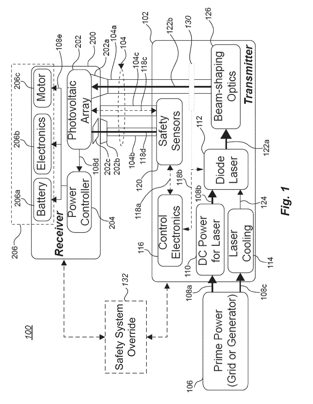
[0037]Power-over-fiber (PoF) systems generally include a high-flux electromagnetic energy transmitter (e.g., a laser light source) and an electromagnetic energy receiver coupled together by a fiber-based conduit (e.g., a fiber optic cable). Light from the high-flux electromagnetic energy transmitter passes through the fiber-based conduit to the electromagnetic energy receiver, and the electromagnetic energy receiver converts the received light into electricity. In many cases, a laser-based system in the electromagnetic energy transmitter generates the high-flux light, and a photovoltaic array in the electromagnetic energy receiver converts the received light into electricity.

[0038]It has been recognized by the inventor that in particular circumstances of PoF systems, improvements in safety may be achieved when a portion of the high-flux light passed from the high-flux electromagnetic energy transmitter is used to control certain operations of the high-flux electromagnetic energy tra...


PUM


Abstract

An electromagnetic energy transmitting device includes a processing unit, a light-detecting sensor coupled to the processing unit, and a high-flux electromagnetic energy transmitter. An electromagnetic energy receiver arranged to convert received light into electricity. A first fiber-based conduit couples the high-flux electromagnetic energy transmitter to the electromagnetic energy receiver. The first fiber-based conduit is arranged to pass high-flux light from the high-flux electromagnetic energy transmitter to the electromagnetic energy receiver. A second fiber-based conduit couples the electromagnetic energy receiver to the light-detecting sensor. The second fiber-based conduit is arranged to pass at least some light from the electromagnetic energy receiver to the light-detecting sensor, wherein the processing unit is arranged to control an output of the high-flux light from the high-flux source based on a control signal from the light-detecting sensor.

Description

BACKGROUNDTechnical Field[0001]The present disclosure generally relates to an optical fiber-based safety system integrated into a power-over-fiber system. More particularly, but not exclusively, the present disclosure relates to a power-over-fiber (PoF) system having a high-flux electromagnetic energy transmitter coupled via a fiber-based conduit and a fiber-based safety system to an electromagnetic energy receiver that converts received light into electricity.Description of the Related Art[0002]Some aspects of technologies and related art that may be useful in understanding the present invention are described in U.S. patent application Ser. No. 14 / 124,993, which is now U.S. Pat. No. 9,800,091 issued to Nugent et al. The Nugent patent describes an aerial platform that receives power in the form of light (e.g., laser light) transmitted via an optical fiber from a remote optical power source. The platform comprises a receiver, which converts at least a portion of the received light to...

Claims


Application Information

Patent Timeline
Patent Type & Authority Applications(United States)
IPC IPC(8): H01L31/054H04B10/80H01L31/052
CPCH01L31/0547H01L31/052H04B10/807Y02E10/52
Inventor NUGENT, JR., THOMAS J.BASHFORD, THOMAS W.BASHFORD, DAVIDHAY, ALEXANDER
Owner LASERMOTIVE
Why Eureka
Try Eureka