Record player
a record player and record technology, applied in the field of record players, can solve the problems of affecting the quality of reproduction of records, the vibration of the drive motor cannot be avoided, and the user's magnetism may be adversely affected, and achieve the effect of little adverse
- Summary
- Abstract
- Description
- Claims
- Application Information
AI Technical Summary
Benefits of technology
Problems solved by technology
Method used
Image
Examples
first embodiment
[Schematic Configuration of Record Player]
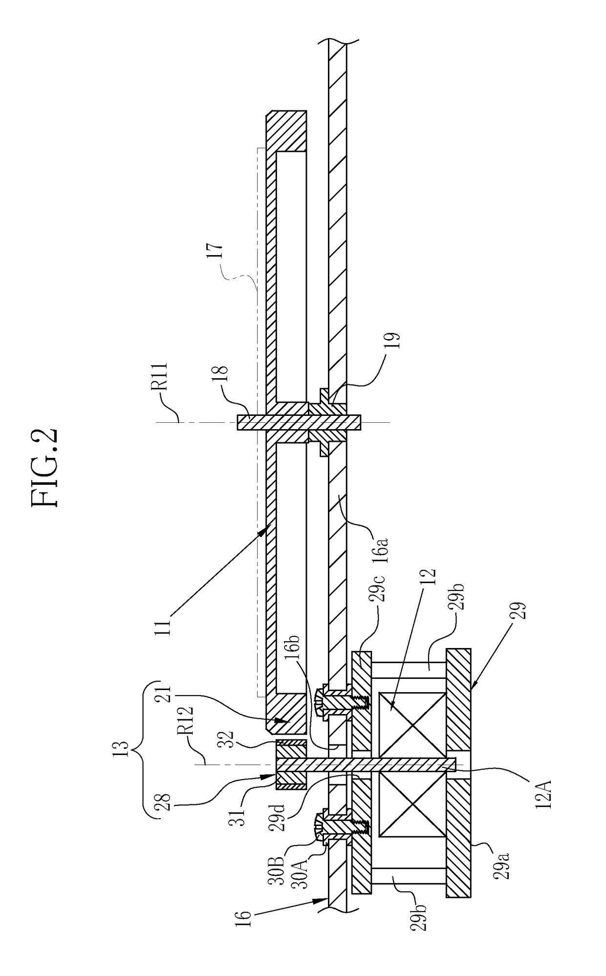
[0045]As shown in FIG. 1, a record player 10 includes a turntable 11, a drive motor 12, a non-contact transmission mechanism 13, a tone arm 14, and a housing 16. The turntable 11 and the tone arm 14 are attached to an upper surface of the housing 16.
[0046]The turntable 11 is a table for rotating a record 17 and has a circular plane shape. The record 17 is placed on a top surface of the turntable 11. A spindle 18 rotatably supports the turntable 11. The spindle 18 and the turntable 11 are engaged by an engaging portion (not shown), and the spindle 18 and the turntable 11 rotate together. In a state where the turntable 11 is attached, the tip of the spindle 18 protrudes from the center of the upper surface of the turntable 11. The tip of the spindle 18 is used to attach the record 17 placed on the turntable 11. A top plate 16a of the housing 16 is provided with a bearing 19 (see FIG. 2). The spindle 18 is inserted into the bearing 19 and rotat...
second embodiment
[0082]FIGS. 6 to 9 illustrate a second embodiment. In the first embodiment, the magnetic member constituting the non-contact transmission mechanism has a gear shape in which the projection portion (first portion) and the recessed portion (second portion) are alternately arranged at regular intervals in the circumferential direction. On the other hand, as shown in FIG. 6, in a record player 40 of the second embodiment, a magnetic member constituting the non-contact transmission mechanism has an annular body formed along the outer periphery of the turntable, with a plurality of opening portions formed at equal intervals in the circumferential direction. In the annular body as the magnetic member, a peripheral surface portion connecting the adjacent opening portions corresponds to the first portion and the opening portion corresponds to the second portion. As described above, the magnetic member is not limited to the uneven shape, and an opening may be used instead of the recessed port...
third embodiment
[0105]FIGS. 10 to 13 illustrate a third embodiment. In the first and second embodiments, the magnetic members 21 and 51 are provided on the side surfaces of the outer peripheral portions of the turntables 11 and 41, which are parallel to the rotation axis of the turntables 11 and 41. On the other hand, as shown in FIG. 10, in a record player 60 of the third embodiment, in the outer peripheral portion of turntable, a magnetic member is provided on a plane orthogonal to the rotation axis of the turntable.
[0106]As same as in the record player 40 of the second embodiment, also in the record player 60 of the third embodiment, the drive-side rotor and the magnetic member are arranged inside the housing, and a transparent plate is provided in the housing so that a portion where the drive-side rotor and the magnetic member face each other is visible from outside. In the third embodiment, the same members as those of the first and second embodiments are denoted by the same reference numerals...
PUM
 Abstract
Description
Claims
Application Information
 - R&D
- Intellectual Property
- Life Sciences
- Materials
- Tech Scout
- Unparalleled Data Quality
- Higher Quality Content
- 60% Fewer Hallucinations
Browse by: Latest US Patents, China's latest patents, Technical Efficacy Thesaurus, Application Domain, Technology Topic, Popular Technical Reports.
© 2025 PatSnap. All rights reserved.Legal|Privacy policy|Modern Slavery Act Transparency Statement|Sitemap|About US| Contact US: help@patsnap.com


