Image sensing device and image sensing method
a technology of image sensing and image, applied in the field of image sensing technique, can solve the problems of increasing the cost, and increasing the cost of image capturing based on such standards, so as to achieve the effect of reducing the cost of hardware configuration
- Summary
- Abstract
- Description
- Claims
- Application Information
AI Technical Summary
Benefits of technology
Problems solved by technology
Method used
Image
Examples
first embodiment
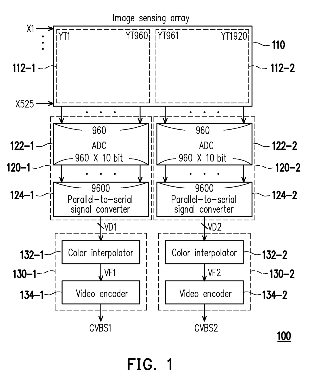
[0020]FIG. 1 is a block diagram illustrating an image sensing device 100 according to the invention. The image sensing device 100 mainly includes an image sensing array 110, a plurality of first signal converters 120-1 and 120-2, and a plurality of first image processing apparatuses 130-1 and 130-2. The image sensing device 100 of the embodiment is applicable in an information system or an electronic apparatus relating to image capturing, such as a surveillance apparatus, a security system and / or the like.
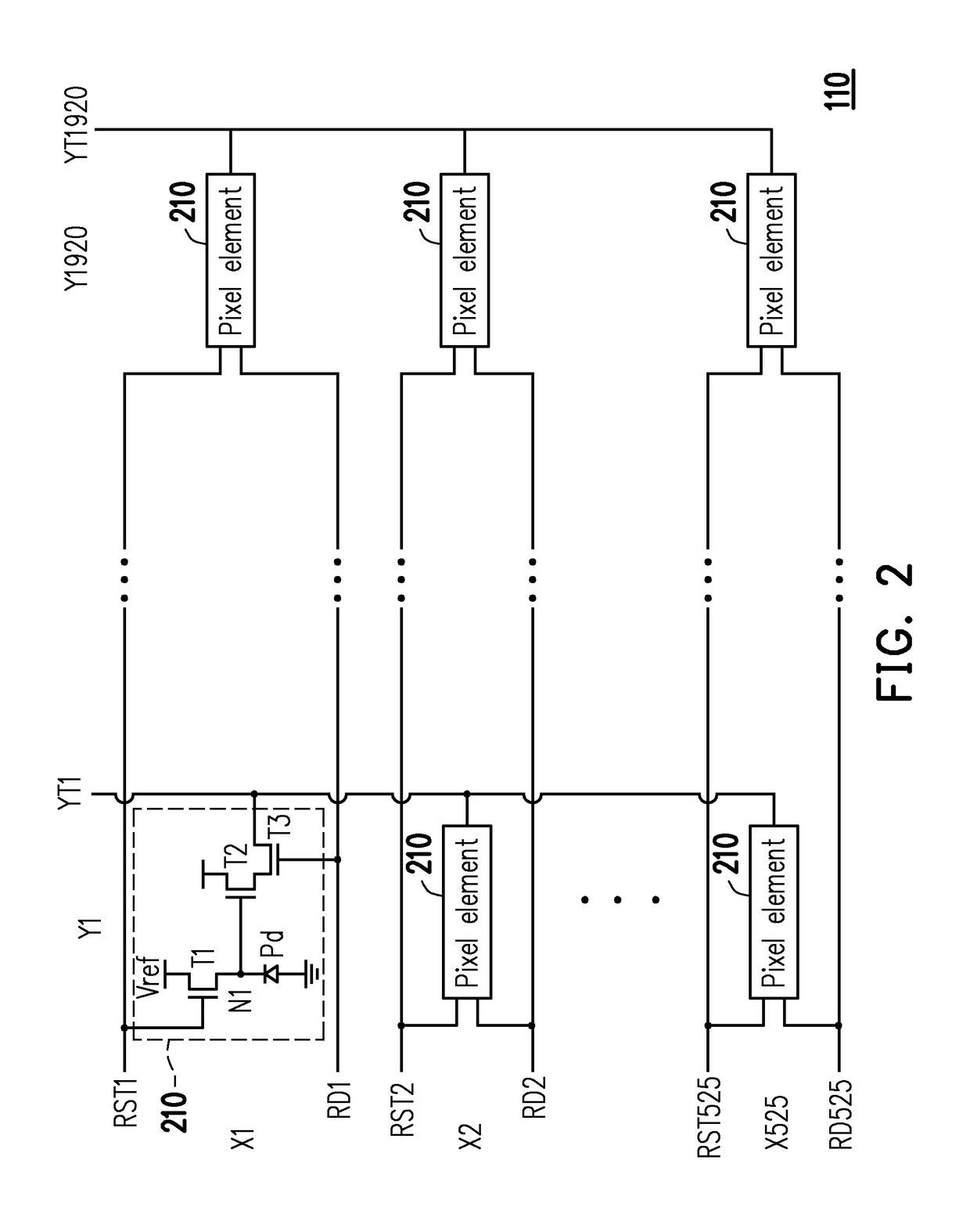
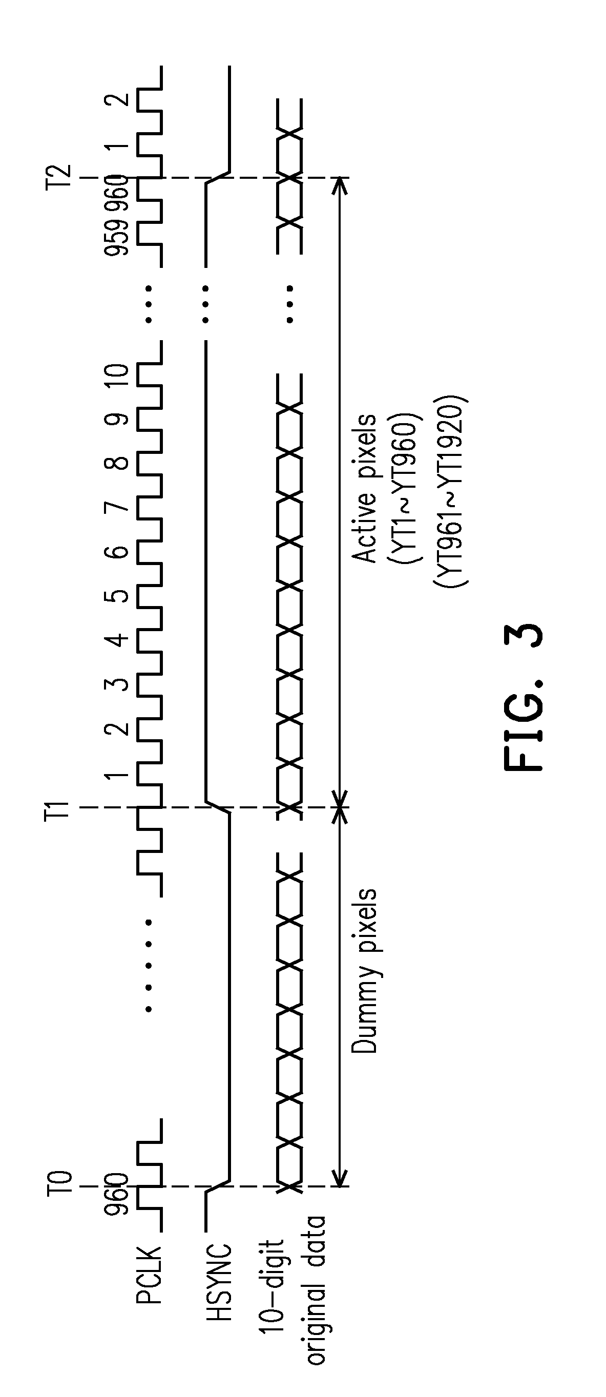
[0021]FIG. 2 is a schematic view illustrating the image sensing array 110 of FIG. 1. Referring to FIG. 2, the image sensing array 110 includes a plurality of pixel elements 210 arranged into columns and rows. The pixel element 210 of the embodiment may include a photodiode Pd and transistors T1 to T3. Assuming that an interlaced scanning system complies with the American National Television System Committee (NTSC) standard, an image may be displayed by being partitioned into odd an...
second embodiment
[0032]FIG. 4 is a block diagram illustrating an image sensing device 400 according to the invention. Compared with FIG. 1, the image sensing device 400 includes an image sensing array in a larger size (i.e., 1050×1920 pixels) and further includes another set of image sensing apparatus in addition to the image sensing apparatus 100 having the first signal converters 120-1 and 120-2 and the first image processing apparatuses 130-1 and 130-2. In other words, the image sensing device 400 further includes a plurality of second signal converters 420-1 and 420-2 and a plurality of second image processing apparatuses 430-1 and 430-2.
[0033]The second signal converters 420-1 and 420-2 and the second image processing apparatuses 430-1 and 430-2 share similar functions and circuit structures with the first signal converter 120-1 and 120-2 and the first image processing apparatuses 130-1 and 130-2 shown in FIG. 1. In addition to the image capturing areas 112-1 and 112-2, the image sensing array ...
third embodiment
[0037]FIG. 5 is a block diagram illustrating an image sensing device 500 according to the invention. What FIG. 5 differs from FIG. 4 is that an image sensing array 510 of the image sensing device 500 of FIG. 5 is in a size of 1050×2880 pixels. Compared with the image sensing array 410 (1050×1920 pixels), the image sensing array 510 is expanded laterally by a certain number of pixels. Therefore, in addition to the pixel capturing areas 112-1, 112-2, 412-1 and 412-2, the image sensing array 510 further includes additional pixel capturing areas 512-1 and 512-2 partitioned in the image sensing array 510. Accordingly, the image sensing device 500 according to an embodiment of the invention may additionally include a plurality of signal converters (e.g., signal converters 520-1 and 520-2) and a plurality of image processing apparatuses (e.g., image processing apparatuses 530-1 and 530-2) to simultaneously process pixels newly added through lateral expansion, such as simultaneously reading...
PUM
 Abstract
Description
Claims
Application Information
 - R&D
- Intellectual Property
- Life Sciences
- Materials
- Tech Scout
- Unparalleled Data Quality
- Higher Quality Content
- 60% Fewer Hallucinations
Browse by: Latest US Patents, China's latest patents, Technical Efficacy Thesaurus, Application Domain, Technology Topic, Popular Technical Reports.
© 2025 PatSnap. All rights reserved.Legal|Privacy policy|Modern Slavery Act Transparency Statement|Sitemap|About US| Contact US: help@patsnap.com


