
Display device and method for fabricating the same

a technology for display devices and manufacturing methods, applied in static indicating devices, identification means, instruments, etc., can solve problems such as increased production costs, defective pixels, and inability to implement display devices of a variety of shapes, and achieve the effect of reducing the bezel area

Active Publication Date: 2019-01-03
LG DISPLAY CO LTD
View PDF10 Cites 19 Cited by
  • Summary
  • Abstract
  • Description
  • Claims
  • Application Information

AI Technical Summary

Benefits of technology

The patent text discusses a display device that uses LED elements, which eliminates the need for an encapsulation layer or substrate, allowing for a reduction in the bezel area. However, when multiple display devices are used in a modular display, it can be difficult to further reduce the inactive area between the devices. The technical effect is the reduction of the bezel area in LED display devices, which makes them more suitable for modular display devices.

Problems solved by technology

In addition, it is not possible to implement a display device having a variety of shapes such as a flexible or circular display device with such a backlight unit.
However, even though an organic light-emitting display device using an organic material does not require an additional light source, there is a problem that a defective pixel may occur due to moisture and oxygen.
Therefore, when a large amount of LEDs are used as light-emitting pixels of a display device, rather than LEDs as a light source used for simple luminaire or a backlight unit, there is a problem that the production cost is increased.
In doing so, it is difficult to separate the LED element from the semiconductor substrate.
Furthermore, it is more difficult to transplant the separated LED element to a designed location correctly.
Such a transfer process is related to the productivity of the process of fabricating display devices, and thus it would be inefficient to transfer the LED elements one by one for mass production.
During the above-described transferring process or subsequent processes that follow the transferring process, there may be defects, e.g., the LED element is flipped over while it is moved or transferred depending on conditions such as vibration or heat.
There were many difficulties in finding and recovering such defects.
In the process of irradiating the laser, when the LED element is separated from the semiconductor substrate, the GaN material of the semiconductor substrate may be physically and rapidly expanded due to concentration of the high energy of the laser, possibly resulting in shock.
Further, unlike organic light-emitting display devices, the influence by oxygen and moisture is ignorable in using an inorganic material.
However, there may be several processing issues in disposing the wirings on the side surface or extending the wirings through holes in the substrate.
However, since such a modular display device is also required to be connected to a circuit board or a circuit part, it may be difficult to further reduce the inactive area which is the bezel area between the display devices.

Method used


Image

  • Display device and method for fabricating the same
  • Display device and method for fabricating the same
  • Display device and method for fabricating the same

Examples


Embodiment Construction

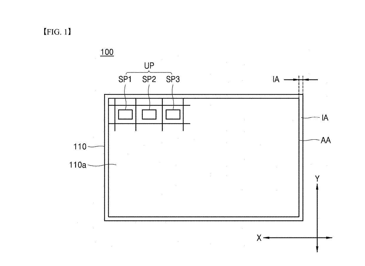
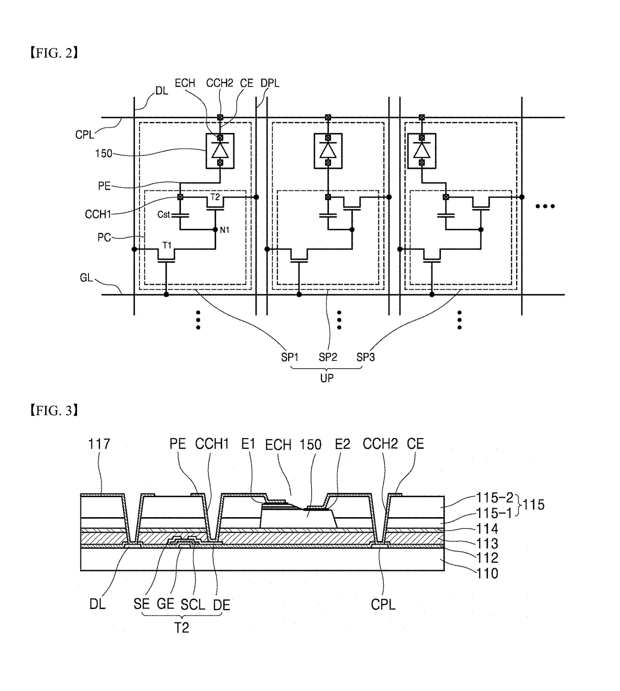
[0082]Advantages and features of the present disclosure and methods to achieve them will become apparent from the descriptions of exemplary embodiments hereinbelow with reference to the accompanying drawings. However, the present disclosure is not limited to exemplary embodiments disclosed herein but may be implemented in various different ways. The exemplary embodiments are provided for making the disclosure of the present disclosure thorough and for fully conveying the scope of the present disclosure to those skilled in the art. It is to be noted that the scope of the present disclosure is defined only by the claims.

[0083]The figures, dimensions, ratios, angles, the numbers of elements given in the drawings are merely illustrative and are not limiting. Like reference numerals denote like elements throughout the descriptions. Further, in describing the present disclosure, descriptions on well-known technologies may be omitted in order not to unnecessarily obscure the gist of the pr...


PUM


Abstract

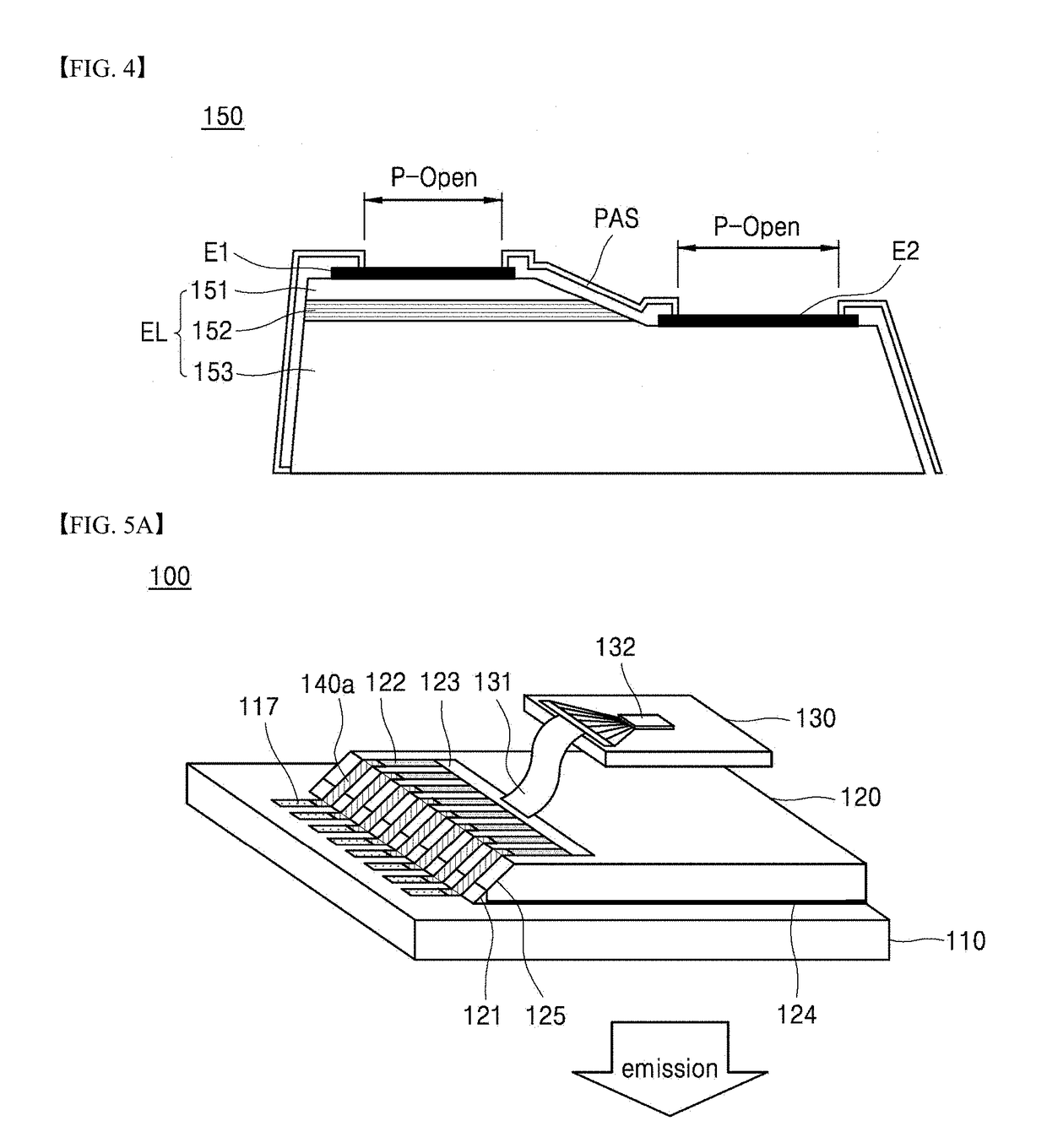
Disclosed herein are a display device with a reduced bezel area and a method for fabricating the same. A wiring electrode disposed on a substrate is electrically connected to a connection electrode disposed on an inclined surface of a circuit board in contact with the substrate, and the connection electrode is electrically connected to a circuit wiring disposed on the circuit board. Therefore, an inactive area such as a pad portion for connecting the substrate with the circuit board is not required, such that the bezel area can be reduced.

Description

CROSS-REFERENCE TO RELATED APPLICATIONS[0001]This application claims the priority of Korean Patent Application No. 10-2017-0083773 filed on Jun. 30, 2017 and Korean Patent Application No. 10-2017-0171254 filed on Dec. 13, 2017, in the Korean Intellectual Property Office, the disclosure of which is hereby incorporated by reference in its entirety.BACKGROUND1. Technical Field[0002]The present disclosure relates to a display device and a method for fabricating the same and more specifically, to a display device in which a bezel area that is an inactive area for connecting electrodes on different substrates can be reduced in the connection structure between the wiring electrode and the circuit board, and a method for fabricating the same.2. Description of the Related Art[0003]A display device is widely used as display screens of a notebook computer, a tablet computer, a smart phone, a portable display device and a portable information device, in addition to display devices of a televisi...

Claims


Application Information

Patent Timeline
Patent Type & Authority Applications(United States)
IPC IPC(8): H01L25/16G09G3/32H01L23/498H01L27/12H01L23/00H01L33/60H01L23/60
CPCH01L25/167G09G3/32H01L23/49833H01L23/49805H01L23/4985H01L27/124H01L24/82H01L24/24H01L25/162H01L33/60H01L23/60H01L24/32H01L24/73G09G2380/02G09G2310/0259G09G2310/0272G09G2300/02H01L2224/24227H01L2224/82103H01L2224/82214H01L33/32H01L2224/32225H01L2224/73217G09F9/33G09G3/3241H05K1/141H05K3/403H05K2201/10106H05K2201/10128H10K59/18H05K2201/09154H05K2201/09781H05K1/092H10K59/123H10K59/131
Inventor LEE, SEUNGCHULLEE, CHANGHOKIM, HANSEOKYUN, MIRA
Owner LG DISPLAY CO LTD
Learn More