Floor Mat with Hidden Base Component
a multi-component, floor mat technology, applied in the direction of magnets, carpet fasteners, magnets, etc., can solve the problems of difficult realignment of the components, difficult alignment of the top textile components on the base component, and the highest floorcovering soiling problem
- Summary
- Abstract
- Description
- Claims
- Application Information
AI Technical Summary
Benefits of technology
Problems solved by technology
Method used
Image
Examples
example 1
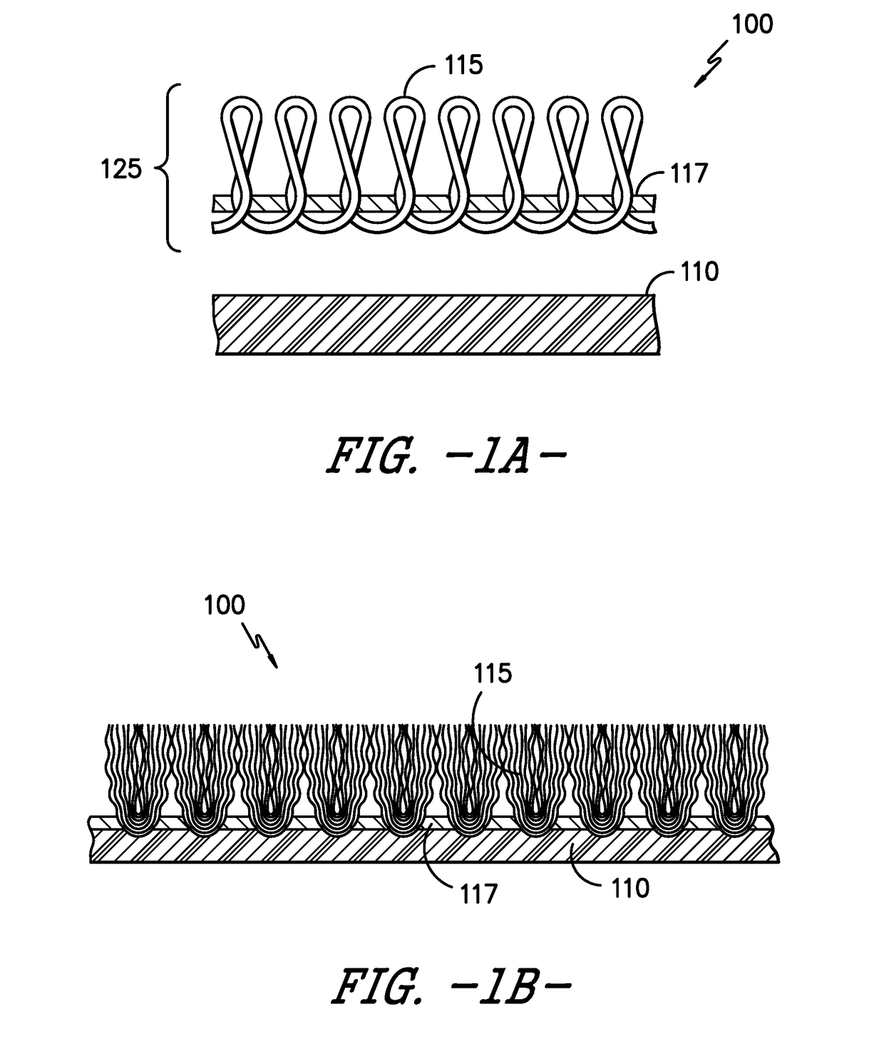
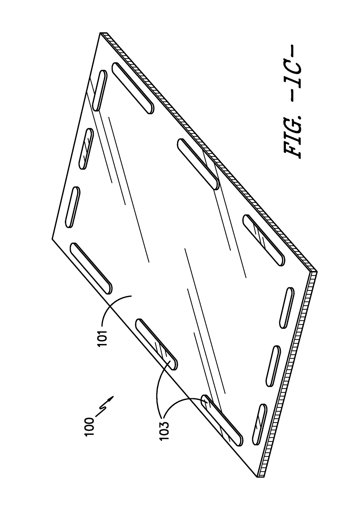
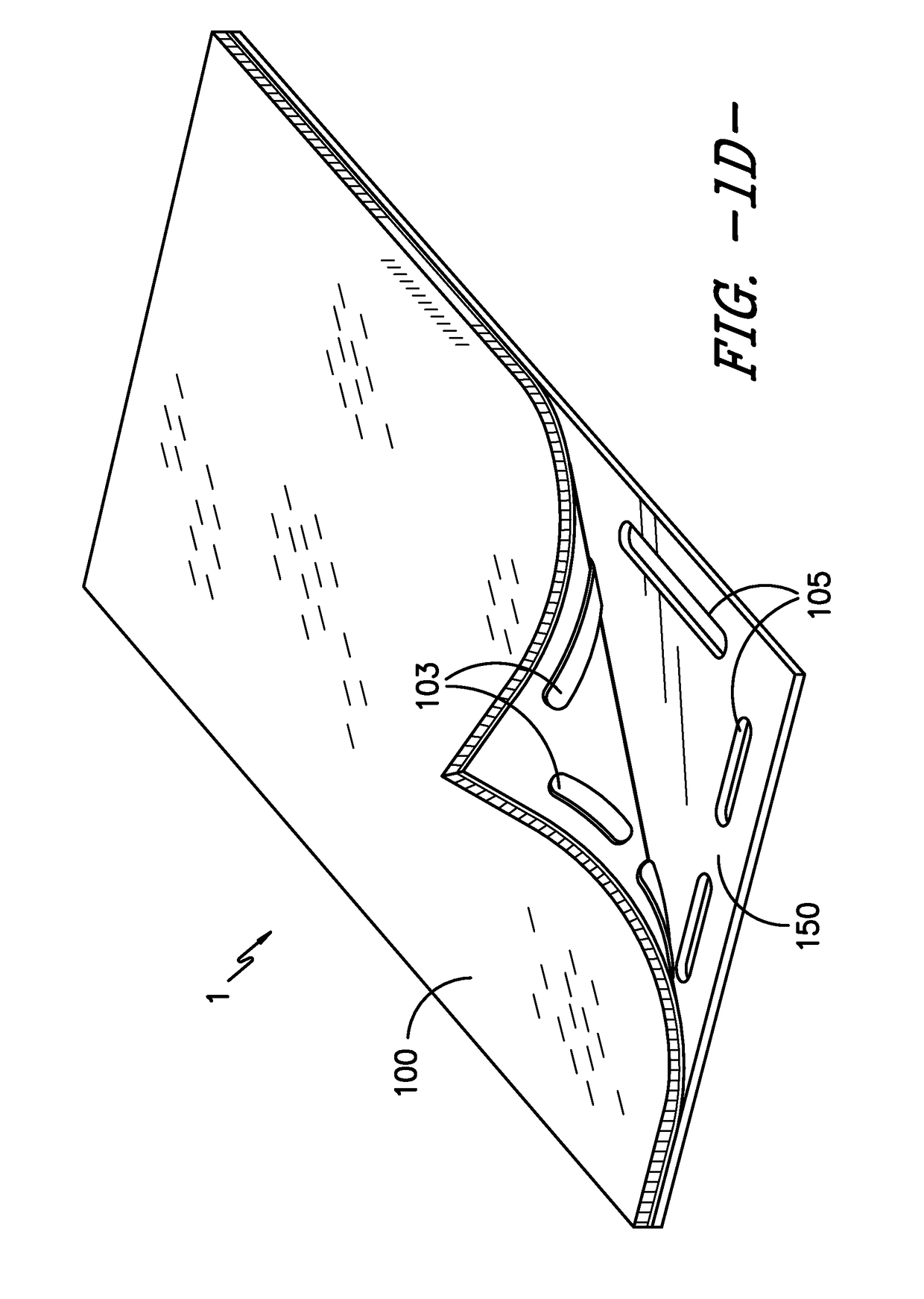
[0139]In this example, the textile component of the floor mat was approximately 3′ wide by 5′ long and the base component was roughly 4″ shorter in both the width and the length, giving a 2″ overlap of the textile component on each side and hiding the base component. The underside of the textile component and the top of the base component were smooth with no protrusions, and the textile component was deployed in a sweeping motion keeping the contact area of the textile component to the base component small until the textile component was mostly over the top of the base component. The textile component was then dropped down on the base component. Because the textile component was substantially oversized compared to the base component, the alignment of the textile component was not critical and the result was that the base component was hidden underneath the textile component. The presence of the base component kept the textile component from undesirable movement during use.
example 2
[0140]In this example, the floor mat of Example 1 was altered so that there was a hook strip of Velcro on the short edge of the base component and a matching strip of loop Velcro on the underside of the textile component. These two strips were positioned so that they were in alignment when the textile component was in alignment with the base component. As the textile component was dragged onto the base component, as in Example 1 above, the two strips of Velcro made physical contact and locked into / onto one another, thus stopping the movement of the textile component and ensuring the forward to back alignment of the components was correct.
example 3
[0141]In this example, the Velcro of Example 2 was replaced with a rubber ridge approximately ⅛″ high extending along the short edge of the textile component and molded into the underside of the textile component; it was positioned in the same place as the Velcro in Example 2. The Velcro on the base component of Example 2 was eliminated, and the rubber ridge of the textile component engaged the edge of the base component so as to provide the same alignment capability of Example 2.
PUM
| Property | Measurement | Unit |
|---|---|---|
| size | aaaaa | aaaaa |
| 90 angle | aaaaa | aaaaa |
| angle | aaaaa | aaaaa |
Abstract
Description
Claims
Application Information
 - R&D
- Intellectual Property
- Life Sciences
- Materials
- Tech Scout
- Unparalleled Data Quality
- Higher Quality Content
- 60% Fewer Hallucinations
Browse by: Latest US Patents, China's latest patents, Technical Efficacy Thesaurus, Application Domain, Technology Topic, Popular Technical Reports.
© 2025 PatSnap. All rights reserved.Legal|Privacy policy|Modern Slavery Act Transparency Statement|Sitemap|About US| Contact US: help@patsnap.com


