
Vehicle control device

a technology of vehicle control and accelerator pedal, which is applied in the direction of vehicle components, transportation and packaging, propulsion unit arrangements, etc., can solve the problems of driver inability to achieve sufficient operation feeling and insufficient and achieve the effect of improving operability and ensuring the operation feeling of accelerator pedal

Inactive Publication Date: 2018-12-27
MAZDA MOTOR CORP
View PDF0 Cites 0 Cited by
  • Summary
  • Abstract
  • Description
  • Claims
  • Application Information

AI Technical Summary

Benefits of technology

This patent describes a vehicle control device that ensures a smooth and safe driving experience for the driver regardless of the type of muscle they use to operate the vehicle. The device uses a reaction force correcting module to adjust the reaction force value based on the operation amount detected by the operation amount detector. This allows for a smooth switch from an agonist muscle to an antagonist muscle, preventing foot wobbling and ensuring smooth operation of the accelerator pedal. Overall, this device improves operability and safety for drivers.

Problems solved by technology

However, in the gentle acceleration / deceleration operation, a sufficient operation feeling of the accelerator pedal may not be secured even when the single articular muscle is caused to function as the agonist muscle to set its contribution ratio higher than that of the biarticular muscle.
That is, in the gentle acceleration / deceleration operation in which the accelerator pedal is finely adjusted, both the agonist muscle and the antagonist muscle are single articular muscles, and merely adjusting the contribution ratios of the single articular muscle and the biarticular muscle does not achieve an easy, smooth switch of the muscle activity from the agonist to the antagonist in shifting from the depression operation to the counter-depression operation, and the driver cannot achieve the sufficient operation feeling.

Method used


Image

  • Vehicle control device
  • Vehicle control device
  • Vehicle control device

Examples


first embodiment

[0042]Hereinafter, a first embodiment of the present disclosure is described with reference to FIGS. 1 to 6.

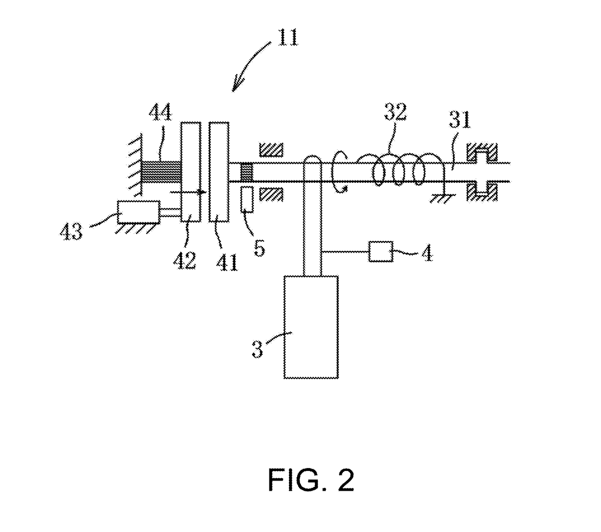
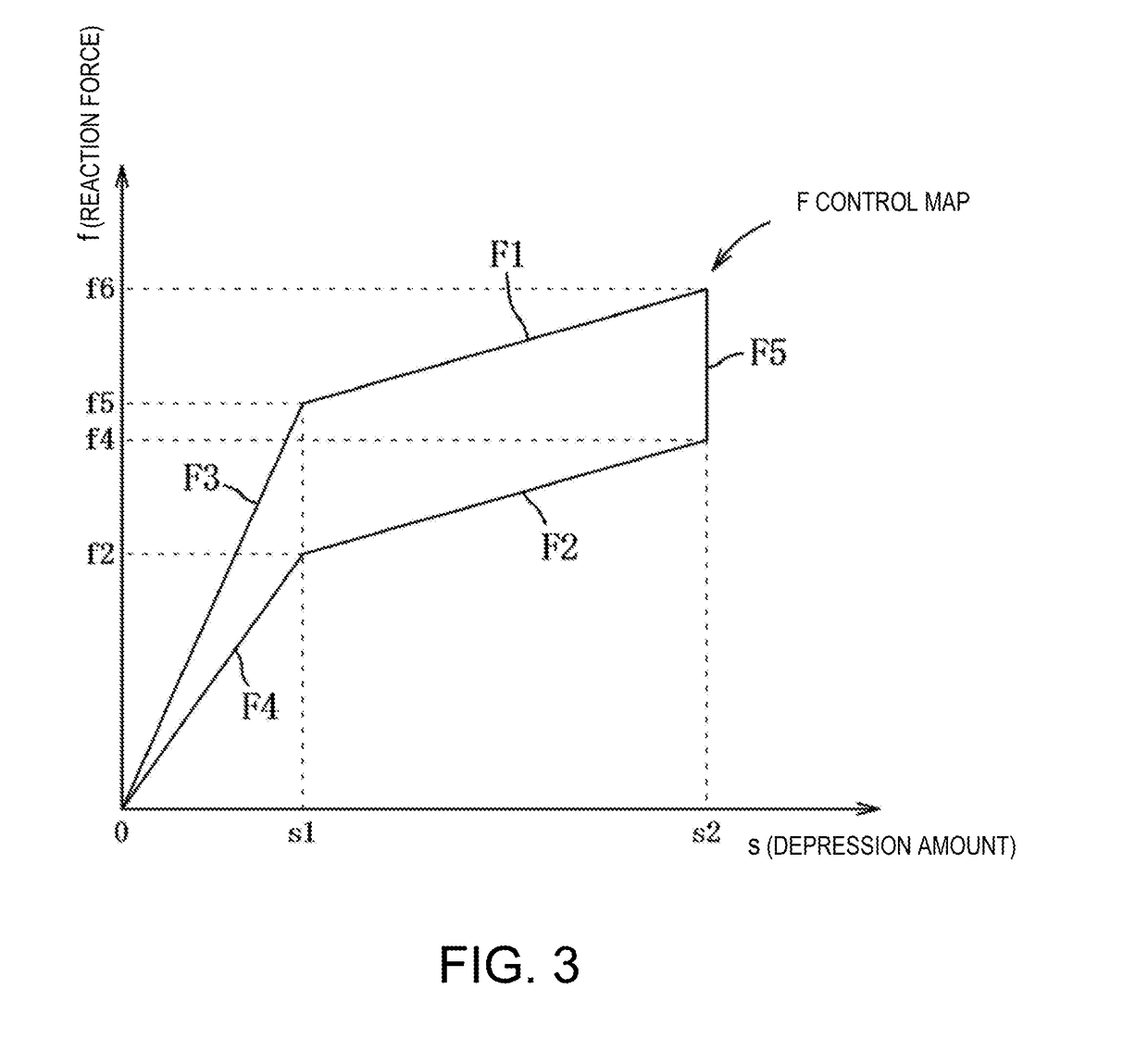
[0043]A vehicle control device 1 controls a reaction force value of an accelerator pedal 3 according to a muscle activity of a vehicle driver so as to provide the driver a realistic feeling in operation regardless of a muscle mainly used in the operation.

[0044]As illustrated in FIG. 1, the control device 1 includes an ECU (Electronic Control Unit) 2. The ECU 2 is an electronic control unit comprised of a processor 25 (i.e., a central processing unit (CPU)) and memory 22 (i.e., ROM(s) and RAM(s)), and performs various arithmetic processes by loading an application program (e.g., a software module) stored in the ROM into the RAM and executes it by the processor 25.

[0045]The ECU 2 is electrically connected to a depression amount sensor 4 (depression amount detector) which detects a depression / counter-depression amount (hereinafter referred to as the depression amount) “s” of the ...


PUM


Abstract

A vehicle control device is provided, which includes a depression amount detector configured to detect a depression amount of an accelerator pedal, a processor configured to execute a reaction force setting module to set a reaction force of the accelerator pedal based on a detection result of the depression amount detector, a reaction force applying part configured to apply the reaction force to the accelerator pedal based on a setting result of the reaction force setting module, and an operation amount detector configured to detect an operation amount of a driver's foot on the accelerator pedal. The reaction force setting module sets a reaction force value of the accelerator pedal for a depression characteristic and a counter-depression characteristic. The reaction force setting module includes a reaction force correcting module configured to reduce the reaction force value of the counter-depression characteristic as the detected operation amount increases.

Description

TECHNICAL FIELD[0001]The present disclosure relates a vehicle control device, which controls a reaction force value of an accelerator pedal according to a vehicle driver's muscle activity.BACKGROUND OF THE DISCLOSURE[0002]Conventionally, in a vehicle equipped with a drive-by-wire type engine, since an accelerator pedal and an output control device of a throttle valve, a fuel injection device, etc. are not connected to each other by a cable, a reaction force at a value corresponding to a depression amount of the accelerator pedal is applied to the driver by an electric actuator.[0003]Since the depression amount and the reaction force value are set to be substantially proportional, the driver generally confirms the depression amount of the accelerator pedal by the reaction force value applied from the accelerator pedal. Therefore, a reaction force control device is proposed, in which a depression operation of an accelerator pedal by a vehicle driver is induced according to the driver'...

Claims


Application Information

Patent Timeline
IPC IPC(8): B60K26/02
CPCB60K26/02B60K2026/026B60Y2300/18008
Inventor YABUNAKA, SHOTAKEDA, YUSAKUTAKAYAMA, MASATOSHI
Owner MAZDA MOTOR CORP
Learn More