Surgical visualization systems and displays
a technology applied in the field of visualization system and display, can solve the problems of prolonged recovery time, pain, scarring, and increased risk of infection, and achieve the effect of reducing stray ligh
- Summary
- Abstract
- Description
- Claims
- Application Information
AI Technical Summary
Benefits of technology
Problems solved by technology
Method used
Image
Examples
embodiment
General Embodiment
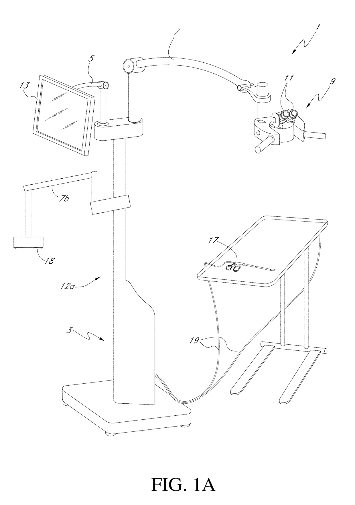
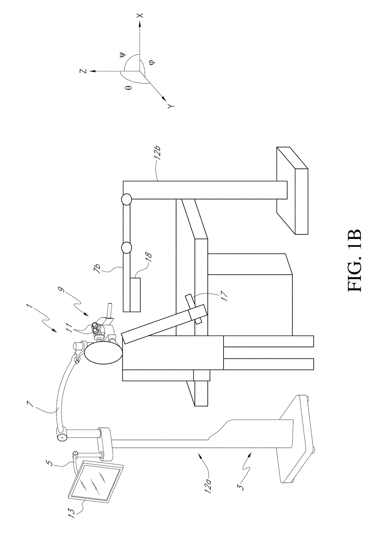
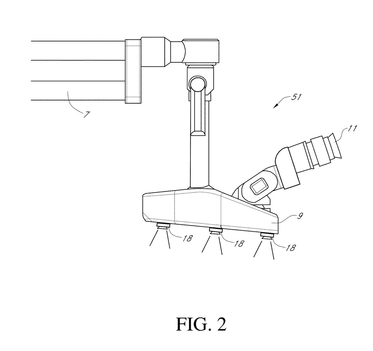
[1299]With continued reference to FIGS. 6A and 6B, in some embodiments, the movement control system 10100 can be attached to an attachment structure, such as binocular display unit 9, and support one or more imagers 18. As shown in the illustrated embodiment, the movement control system 10100 can be oriented generally underneath the binocular display unit 9 and in some embodiments can be sized such that the movement control system 10100 does not extend significantly beyond the outer housing of the binocular display unit 9. This can advantageously provide a smaller form factor thereby reducing the likelihood that the movement control system 10100 will interfere with the medical professionals and assistants during a medical procedure. In other embodiments, the attachment structure can be other components of the surgical visualization system 1 such as, but not limited to, a dedicated articulating arm or a display arm. In some embodiments, the movement control system 1...
example set i
Example 1
[1826]A surgical visualization system for providing visualization of a surgical site, said surgical visualization system comprising:[1827]a first support comprising a first movable arm;[1828]a viewing platform mounted to a distal end of the first movable arm, said viewing platform configured to display images for viewing by a user at said viewing platform;[1829]a second support comprising a second movable arm, the second support separate from the first support;[1830]a camera mounted to a distal end of the second movable arm, said camera configured to provide a surgical microscope view of a surgical site that can be viewed by said user at said viewing platform; and[1831]a control system comprising electronics configured to receive input from the user to move the second movable arm so as to adjust the position and / or orientation of the camera in response to the input from the user.
Example 2
[1832]The surgical visualization system of Example 1, wherein at least one of the first...
example set ii
Example 1
[1853]A surgical visualization system for providing visualization of a surgical site, said surgical visualization system comprising:[1854]a support comprising a movable arm;[1855]a display unit mounted to a distal end of the movable arm, said display unit comprising at least one display disposed in a housing, said display unit comprising left and right eye paths including said at least one display for presenting images to left and right eyes, respectively, of the user, said display unit configured to receive images from one or more cameras configured to image a surgical site, said movable arm configured such that said movable arm can be moved to position the display unit in front of the user's eyes for the user to view images with said display unit and moved to position the display unit away from said user such that said user can view said surgical site without said display unit; and[1856]an image processing system configured to display images of said surgical site obtained...
PUM
 Abstract
Description
Claims
Application Information
 - R&D
- Intellectual Property
- Life Sciences
- Materials
- Tech Scout
- Unparalleled Data Quality
- Higher Quality Content
- 60% Fewer Hallucinations
Browse by: Latest US Patents, China's latest patents, Technical Efficacy Thesaurus, Application Domain, Technology Topic, Popular Technical Reports.
© 2025 PatSnap. All rights reserved.Legal|Privacy policy|Modern Slavery Act Transparency Statement|Sitemap|About US| Contact US: help@patsnap.com


