Scroll compressor

a compressor and compressor technology, applied in the direction of machines/engines, rotary/oscillating piston pump components, liquid fuel engines, etc., can solve the problems of insufficient compression loss, over-compression loss, improper compression loss, etc., and achieve the effect of improving the efficiency of the scroll compressor and minimizing the leakage loss of refrigerant through the sub-discharge por

Active Publication Date: 2018-12-20
MITSUBISHI ELECTRIC CORP
View PDF0 Cites 0 Cited by
  • Summary
  • Abstract
  • Description
  • Claims
  • Application Information

AI Technical Summary

Benefits of technology

[0009]In the scroll compressor according to one embodiment of the present, in the opening portion of the sub-discharge port, the distance between the opening portion and the inward-facing surface or the outward-facing surface of the fixed-scroll volute and the length of the each of the pair of connecting portions in the radial direction of the volute shape are determined so as not to cause the first compression chamber and the second compression chamber to communicate with each other in any phase during one revolution of the orbiting scroll. Therefore, the sub-discharge ports can be prevented from working as bypass passages between the adjacent compression chambers which are different from each other in pressure during the rotation of the orbiting scroll. Further, in the opening portion of each of the sub-discharge ports on the compression chamber side, the pair of side portions extending in the circumferential direction of the volute shape is formed longer than the pair of connecting portions extending in the radial direction of the volute shape. As a result, a necessary opening area and a necessary opening interval of each of the sub-discharge ports can be ensured. Therefore, a necessary over-compression loss reduction effect can be obtained while a refrigerant leakage loss via the sub-discharge ports is minimized. Thus, efficiency of the scroll compressor can be improved.

Problems solved by technology

In general, an improper compression loss is not caused under an operating condition in which a proper compression ratio accords with the built-in volume ratio; however, an over-compression loss is caused under an operating condition in which the compression ratio is smaller than the built-in volume ratio, and an insufficient compression loss is caused under an operating condition in which the compression ratio is greater than the built-in volume ratio.
Under a condition other than a condition under which the proper compression is achieved, an improper compression loss is caused by an over compression or insufficient compression.

Method used


Image

  • Scroll compressor
  • Scroll compressor
  • Scroll compressor

Examples


embodiment 1

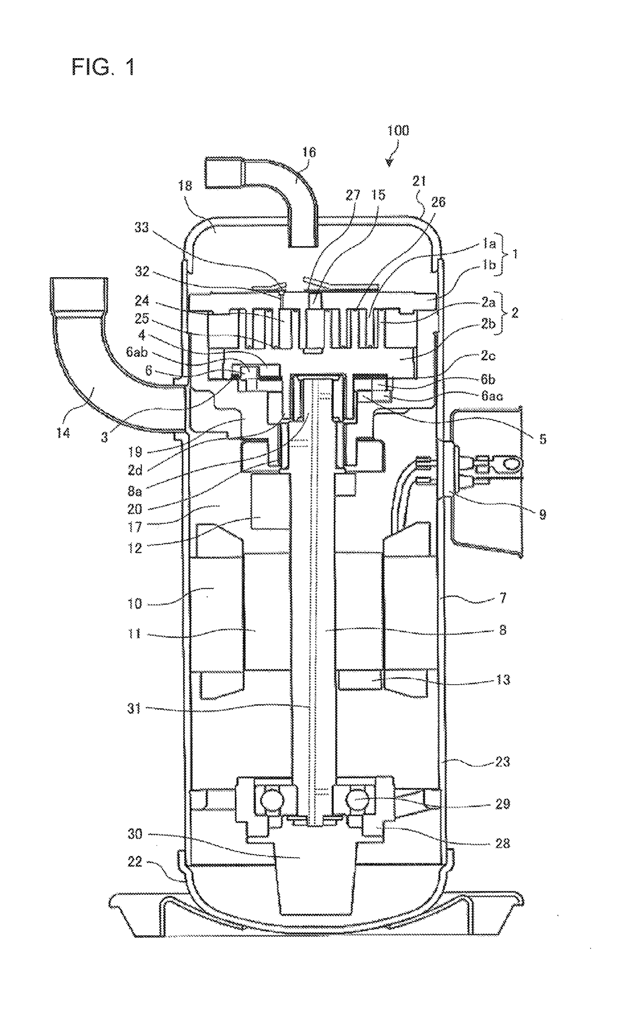
[0015]FIG. 1 is a schematic longitudinal sectional view for schematically illustrating an overall structure of a scroll compressor according to Embodiment 1 of the present invention. With reference to FIG. 1, a configuration and an operation of a scroll compressor 100 will be described. The scroll compressor 100 is one of structural elements of a refrigeration cycle for use in various industrial machines, for example, refrigerators, freezers, automatic vending machines, air-conditioning apparatus, refrigerating devices, and water heaters.

[0016]The scroll compressor 100 is configured to take in refrigerant which circulates in a refrigeration cycle, compress the refrigerant to a high-temperature and a high-pressure state and discharge the refrigerant. The scroll compressor 100 includes an airtight container 23 including a center shell 7, an upper shell 21, and a lower shell 22. The airtight container 23 includes a compression mechanism therein, which is a combination of a fixed scroll...

embodiment 2

[0036]FIG. 3 is a planar volute shape view for illustrating a volute shape of the fixed scroll, a volute shape of the orbiting scroll, and the sub-discharge ports of the scroll compressor according to Embodiment 2 of the present invention. FIG. 4 is a sectional view taken along the arrow A-A of FIG. 3. In part of FIG. 3 which illustrates the entire volute plane, the fixed-scroll volute 1a is indicated by a solid line and the orbiting-scroll volute 2a is indicated by a broken line to clearly illustrate the fixed-scroll volute 1 and the orbiting-scroll volute 2a. Further, in part of the figure which enlargedly illustrates a part of the volute plane, a region of each portion is hatched as appropriate to be clearly defined.

[0037]Each of sub-discharge ports 320 according to Embodiment 2 has a compression-chamber-side end portion 322 which is open to the compression chamber 24 side and a base portion 321 which is continuous with the compression chamber-side end portion 322 and is open to ...


PUM


Abstract

A scroll compressor including an orbiting scroll and a fixed scroll. A compression chamber is formed by combining a fixed-scroll volute of the fixed scroll and an orbiting-scroll volute of the orbiting scroll. Each of sub-discharge ports of the fixed scroll brings any one of a first compression chamber and a second compression chamber of a compression chamber, the first compression chamber being defined by an inward-facing surface of the fixed-scroll volute and an outward-facing surface of the orbiting-scroll volute, the second compression chamber being defined by an outwardfacing surface of the fixed-scroll volute and an inward-facing surface of the orbiting scroll volute, and a discharge side into communication with each other.

Description

TECHNICAL FIELD[0001]The present invention relates to a scroll compressor to be used for refrigeration and air-conditioning, and more particularly, to a scroll compressor which is supposed to be operated in a wide range of compression ratio and a wide range of rotation speed as in an air-conditioning use.BACKGROUND ART[0002]In scroll compressors, a built-in volume ratio is determined in accordance with volute specifications. In general, an improper compression loss is not caused under an operating condition in which a proper compression ratio accords with the built-in volume ratio; however, an over-compression loss is caused under an operating condition in which the compression ratio is smaller than the built-in volume ratio, and an insufficient compression loss is caused under an operating condition in which the compression ratio is greater than the built-in volume ratio.[0003]Therefore, generally, the scroll compressors adopt volute specifications for a built-in volume ratio accor...

Claims


Application Information

Patent Timeline
Patent Type & Authority Applications(United States)
IPC IPC(8): F04C18/02
CPCF04C18/0292F04C18/0215F04C2240/50F04C2210/268F04C28/26F04C29/128F04C18/02F04C18/0261
Inventor TATSUWAKI, KOHEIMATSUI, TOMOKAZUKOYAMA, SHUHEITAKAMURA, YUJI
Owner MITSUBISHI ELECTRIC CORP
Why Eureka
Try Eureka