Portable in-exsufflator

a portable, in-exsufflator technology, applied in respiratory masks, medical devices, other medical devices, etc., can solve the problems of large flow loss, large discharge noise, long length of flow path, etc., to minimize flow loss, reduce discharge noise during exhalation, and maximally simplify air flow path

Inactive Publication Date: 2018-12-20
SEOIL PACIFIC CORP
View PDF10 Cites 1 Cited by
  • Summary
  • Abstract
  • Description
  • Claims
  • Application Information

AI Technical Summary

Benefits of technology

[0028]In order to accomplish the present invention, a portable in-exsufflator according to the present invention is provided with an air pressure generation unit in a direction perpendicular to the manifold, thereby minimizing the flow loss by maximally simplifying an air flow path.
[0029]Also, the portable in-exsufflator according to the present invention forms a flow path configured to introduce external air during inhalation, discharges the air through a central flow path of the high-frequency oscillation wave generation means during exhalation, and blocks air from flowing into an air intake port of the air pressure generation unit during exhalation, so that the inlet configured to introduce the external air and the discharge port configured to discharge the air exhaled from the patient can be completely separated and a discharge noise during the exhalation can be reduced.
[0030]Also, the portable in-exsufflator according to the present invention can control an oscillation and amplitude of a high-frequency oscillation wave generation means 40 by feeding back a pressure in an inhalation mode IN and an exhalation mode EX by removing a position sensing magnet provided on an upper part of the conventional moving body and a center position sensing sensor provided on an outside of the magnet.
[0031]Further, the portable in-exsufflator according to the present invention communicates flow paths of a respiratory flow port and an external air flow port in a pause mode so that a patient can breathe under atmospheric pressure conditions, thereby providing a comfortable resting function to the patient.

Problems solved by technology

However, in the conventional portable in-exsufflator, since the manifold 1 and the air pressure generation unit 2 are horizontally installed, the length of a flow path becomes long and thus a flow loss is great.
Further, in the conventional portable in-exsufflator, fresh external air and exhaled air are likely to be mixed with each other due to the external air introduced into the external air flow port 1d being discharged through the same passage as that of the air exhaled from the patient's respiratory organs, and there is a problem in that the discharged air is directly discharged to the external air flow port 1d, which can cause a great discharge noise.
Also, in the inhalation mode IN and the exhalation mode EX, the oscillation and amplitude control of the high-frequency oscillation wave generation means 4 is controlled by the center position sensing sensor 4d and the position sensing magnet 4c, and thus accurate control is difficult.
Also, in the pause mode, there is a problem in that the flow paths of the respiratory flow port 1g and the external air flow port 1d do not communicate with each other, and therefore the patient is not breathing under atmospheric pressure conditions.

Method used


Image

  • Portable in-exsufflator
  • Portable in-exsufflator
  • Portable in-exsufflator

Examples


Embodiment Construction

[0045]Hereinafter, the structure and function of the embodiment of the present invention will be described with reference to the accompanying drawings.

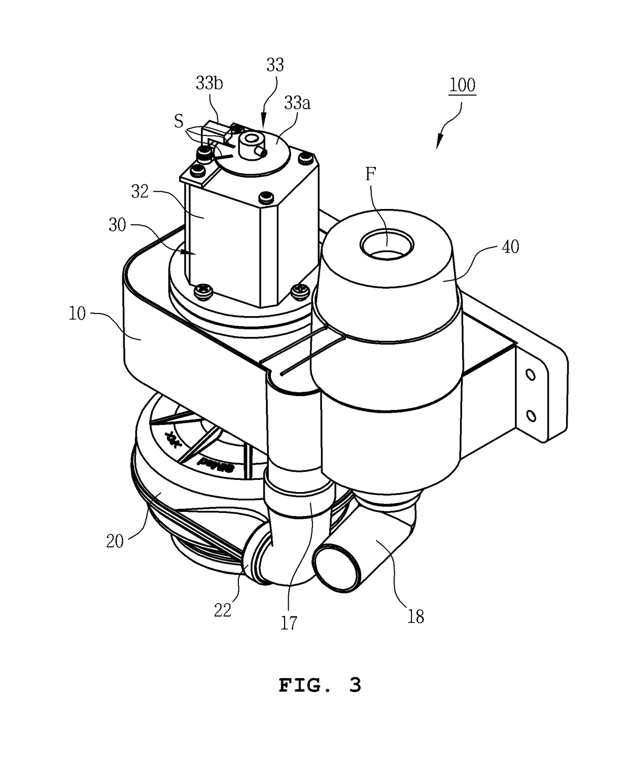
[0046]Referring to the FIGS. 3 to 10, a portable in-exsufflator 100 according to the present invention includes a manifold 10, an air pressure generation unit 20, a direction-switching valve unit 30, and a high-frequency oscillation wave generation means 40.

[0047]The manifold 10 has a first accommodation part 11 and a second accommodation part 12 formed at an upper part thereof and an inhalation chamber 13 and an exhalation chamber 14 formed at a lower part thereof.

[0048]Also, a plurality of communication ports 15 are formed around the first accommodation part 11 of the manifold 10, and each of the communication ports 15 communicates with an external air flow port 16, an inhalation chamber 13, and an exhalation chamber 14.

[0049]Also, the communication ports 15 communicating with the inhalation chamber 13 and the exhalation chamber 14 ...


PUM


Abstract

The present invention relates to a portable in-exsufflator, and the objective of the present invention is to provide a portable in-exsufflator for maximally simplifying an air passage so as to minimize a flow loss.The in-exsufflator comprises: a manifold having a first accommodation part and a second accommodation part, which are formed at an upper part thereof, and an inhalation chamber and an exhalation chamber, which are formed at a lower part thereof; an air pressure generation unit for suctioning and discharging air by means of a fan rotating by a rotational force transmitted from a motor, and having an air suction port connected to the inhalation chamber and an air discharge port connected to the second accommodation part; a direction-switching valve unit coupled to the first accommodation part, and switching a direction so as to allow external air to flow therein and be supplied to respiratory organs or to suction the air from the respiratory organs by using the air pressure generated from the air pressure generation unit; and a high-frequency oscillation wave generation means coupled to the second accommodation part, and generating a high-frequency oscillation wave when the external air having flowed therein is supplied to the respiratory organs or the air is suctioned from the respiratory organs, wherein a plurality of communication ports are formed around the first accommodation part of the manifold such that the communication ports respectively communicate with an external air flow port, the inhalation chamber and the exhalation chamber.

Description

TECHNICAL FIELD[0001]The present invention relates to a portable in-exsufflator, and more specifically, to a portable in-exsufflator for maximally simplifying an air flow path so as to minimize a flow loss.BACKGROUND ART[0002]Coughing is one of the important defensive actions of our body and prevents harmful substances such as gas, bacteria, or the like, or various foreign substances from entering an airway.[0003]Coughing also helps to ensure that the airway is kept clean at all times by allowing suctioned foreign substances or intra-airway secretions to be discharged from the airway.[0004]Accordingly, for example, for patients with impaired coughing function, such as neuromuscular patients with respiratory muscle paralysis, or patients with a restrictive pulmonary disease, pneumonia is caused by foreign substances or secretions block an airway to cause a dyspnea phenomenon.[0005]A cough assist device has been developed to protect a patient from such a risk, and a conventional examp...

Claims


Application Information

Patent Timeline
Patent Type & Authority Applications(United States)
IPC IPC(8): A61M16/00A61M16/08A61M16/20
CPCA61M16/0069A61M16/0006A61M16/0875A61M16/204A61M16/024A61M2016/0015A61M16/00A61M2205/3331A61M2016/0027A61M16/06A61M16/08A61M16/20A61M16/202
Inventor KIM, GYE CHEOLKIM, CHIL HWAN
Owner SEOIL PACIFIC CORP
Why Eureka
Try Eureka