
Device and method for generating forward directed shock waves

a forward directed and shock wave technology, applied in the field of generation of shock waves, can solve the problems of stressing and injuring the vessel walls, and reducing the efficiency of the shock wave generation process

Active Publication Date: 2018-12-20
SHOCKWAVE MEDICAL
View PDF4 Cites 18 Cited by
  • Summary
  • Abstract
  • Description
  • Claims
  • Application Information

AI Technical Summary

Benefits of technology

The patent describes a shock wave device and method for treating plaques or obstructions in vessels, such as blood vessels and ureters. The device includes an outer covering and an inner member with conductive wires that can initiate shock waves. The device can be introduced into a vessel and positioned to face a treatment region. A high voltage pulse is applied across the wires to initiate shock waves that propagate in a forward direction. The device can also include an angioplasty balloon or secondary emitter bands to further treat the vessel. The technical effects of the patent include improved treatment of plaques and obstructions in vessels with a shock wave device.

Problems solved by technology

As the pressure builds, a tremendous amount of energy is stored in the balloon until the calcified lesion breaks or cracks.
That energy is then released and results in the rapid expansion of the balloon to its maximum dimension and may stress and injure the vessel walls.
Unfortunately, many times the physician is faced with a chronic occlusion which is not passable with a guide wire.
Unfortunately, the heat generated by the radio frequency energy to open the occlusion is intense and can damage the walls of the artery or vessel.
Such centering is difficult to achieve, especially in the corners and bends of the arteries or veins.

Method used


Image

  • Device and method for generating forward directed shock waves
  • Device and method for generating forward directed shock waves
  • Device and method for generating forward directed shock waves

Examples


Embodiment Construction

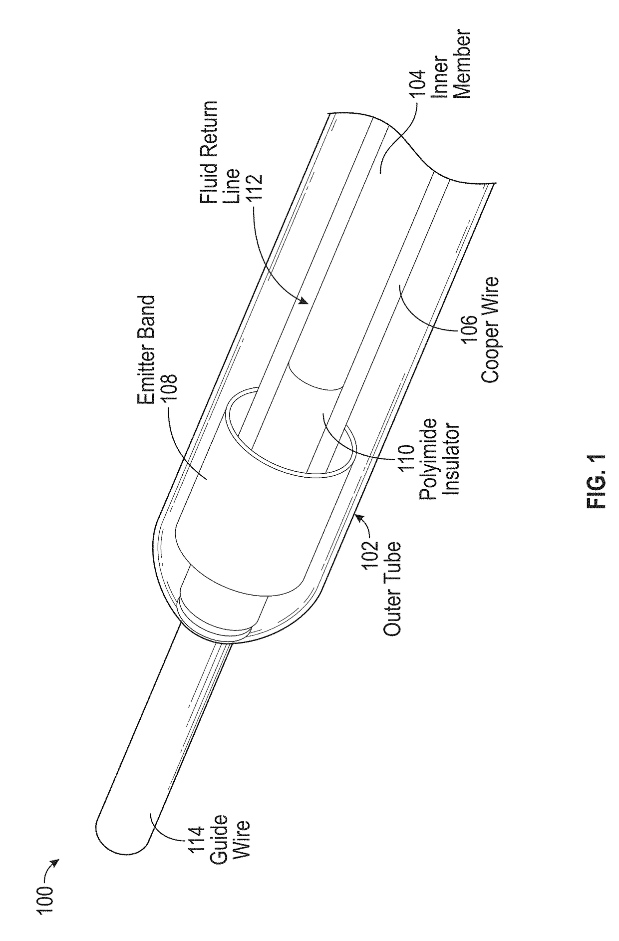
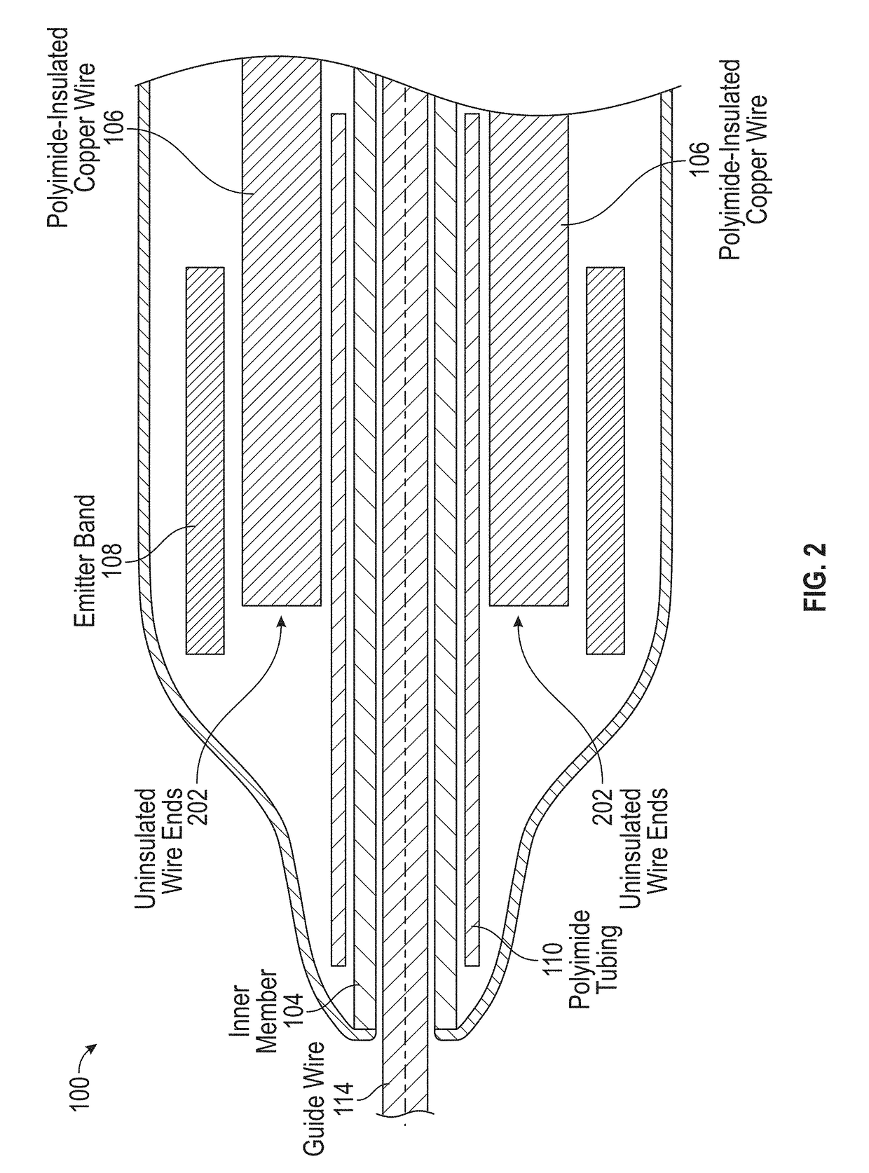
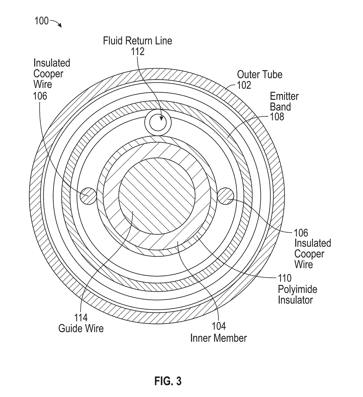
[0020]Described herein are devices, systems, and methods for generating shock waves that propagate in a substantially forward direction to treat vascular diseases, such as chronic total occlusion (CTO) or circumferential calcium, or to treat urinary diseases, such as concretions or kidney stones in the ureter. In accordance with the present disclosure, a shock wave device includes an outer covering and an inner member forming a guide wire lumen. The outer covering and inner member are connected at a distal end of the device. A first conductive wire and a second conductive wire extend along the length of the device within the volume between the outer covering and the inner member, and end proximate to the distal end of the device. A conductive emitter band circumscribes the ends of the first and second wires to form a first spark gap between the end of the first wire and the emitter band and a second spark gap between the end of the second wire and the emitter band.

[0021]When the vol...


PUM


Abstract

Described herein is a shock wave device for the treatment of vascular occlusions. The shock wave device includes an outer covering and an inner member inner connected at a distal end of the device. First and second conductive wires extend along the length of the device within the volume between the outer covering and the inner member. A conductive emitter band circumscribes the ends of the first and second wires to form a first spark gap between the end of the first wire and the emitter band and a second spark gap between the end of the second wire and the emitter band. When the volume is filled with conductive fluid and a high voltage pulse is applied across the first and second wires, first and second shock waves can be initiated from the first and second spark gaps.

Description

PRIORITY[0001]This application claims priority to provisional application Ser. No. 62 / 521,994, filed Jun. 19, 2017, the entire disclosure of which is incorporated by reference.FIELD[0002]The present disclosure relates generally to the generation of shock waves, and, more specifically, to the generation of shock waves within vascular or urinary structures.BACKGROUND[0003]The subject invention relates to treating calcified lesions in blood vessels, or obstructions in other vessels, such as kidney stones in ureters. One common approach to addressing this issue is balloon angioplasty. In this type of procedure, a catheter, carrying a balloon, is advanced into the vasculature along a guide wire until the balloon is aligned with the occlusion. The balloon is then pressurized in a manner to reduce or break the occlusion. When inflated to high pressures, angioplasty balloons can have a specific maximum diameter to which they will expand. Generally, the opening in the vessel under a concentr...

Claims


Application Information

Patent Timeline
Patent Type & Authority Applications(United States)
IPC IPC(8): A61B17/22A61M25/10A61M5/00
CPCA61B17/22022A61M25/104A61M25/10181A61M25/10186A61M5/007A61B2017/22025A61B2017/22001A61B2017/22062A61M2025/1079A61B2017/22028A61B2017/22038A61M2210/12A61M2210/1082A61B17/2202A61B2017/22051
Inventor NGUYEN, HOA D.
Owner SHOCKWAVE MEDICAL
Learn More