
Measurement error correction method based on temperature-dependent displacement in measurement device and mass spectrometer using the same method

Active Publication Date: 2018-12-13
SHIMADZU CORP
View PDF0 Cites 6 Cited by
  • Summary
  • Abstract
  • Description
  • Claims
  • Application Information

AI Technical Summary

Benefits of technology

The present invention provides a measurement error correction method based on temperature-dependent displacement in a measurement device. This method can accurately correct errors or discrepancies in measurement data caused by thermal expansion of a component member in the device without significantly increasing the cost of the device. Additionally, a mass spectrometer according to the present invention employing the present measurement error correction method can achieve a high level of mass accuracy without significantly increasing the cost of the device.

Problems solved by technology

For example, materials which have low coefficients of thermal expansion, such as Fe—Ni36%, are expensive as compared to commonly used kinds of metal, such as stainless steel.
Using a material having a low coefficient of thermal expansion for such a member inevitably leads to a dramatic increase in the cost of the device.
Placing a flight tube within an insulated container as in the device described in Non Patent Literature 1 also causes a dramatic increase in the cost of the device.
On the other hand, in the case of the correction using the result of a measurement of a reference sample, it is necessary to prepare the reference sample, and the analysis operator is forced to bear that burden.
Furthermore, performing a measurement of a reference sample other than a measurement target component may cause the problem of a contamination in the device or a deterioration in the throughput of an analysis for the measurement target component.
However, laser distance meters are expensive and lead to a dramatic increase in the cost of the device.

Method used


Image

  • Measurement error correction method based on temperature-dependent displacement in measurement device and mass spectrometer using the same method

Examples


Embodiment Construction

[0034]A time-of-flight mass spectrometer (TOFMS) as one embodiment of the mass spectrometer employing a measurement error correction method based on a temperature-dependent displacement in a measurement device according to the present invention is hereinafter described with reference to the attached drawings.

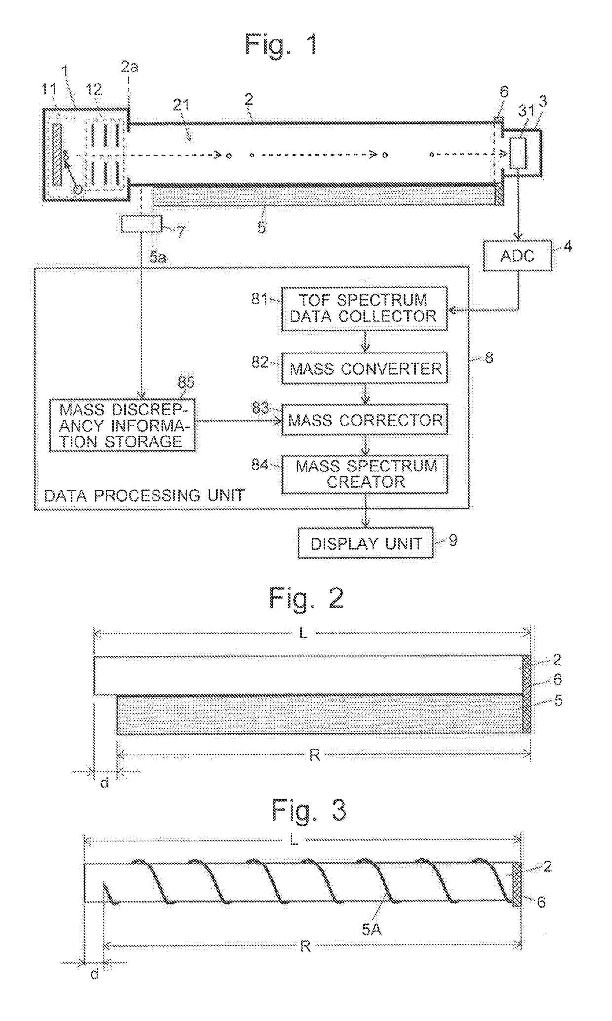
[0035]FIG. 1 is a configuration diagram of the main components of the TOFMS according to the present embodiment.

[0036]The TOFMS according to the present embodiment includes an ionization chamber 1 containing an ionizer 11 and an accelerator 12, as well as a detection chamber 3 containing a detector 31. The two chambers are respectively attached to the two end faces of a flight tube 2 having a substantially cylindrical shape. A predetermined level of direct voltage +V is applied to the metallic flight tube 2. A flight space 21 having a high vacuum atmosphere with neither an electric field nor a magnetic field is created within the flight tube 2.

[0037]Ions are generated from a sam...


PUM


Abstract

A columnar rod reference member made of a material whose coefficient of thermal expansion is different from a flight tube is placed in contact with the tube. One end of the tube and o the reference member are fixed to each other with a fixture part. A distance measurement sensor measures the difference in length between the tube and the reference member whose lengths fluctuate due to a change in temperature. A displacement of the difference in length, as expressed by a proportion, is larger than that of the length of the flight tube. The difference in length is far smaller than the length of the flight tube. This improves detection of the displacement due to thermal expansion with a strain gauge or sensor. The m / z values in mass spectrum data are corrected based on the measured values of the displacement, whereby a highly accurate mass discrepancy correction is achieved.

Description

TECHNICAL FIELD[0001]The present invention relates to a method for correcting an error or discrepancy in measurement data caused by a thermal expansion of various component members in a measurement device, as well as a mass spectrometer using the same method.BACKGROUND ART[0002]In a normal type of time-of-flight mass spectrometer (TOFMS), a fixed amount of acceleration energy is imparted to ions derived from a sample component. The ions are introduced into a field-free flight space formed within a flight tube and made to fly in the same space. For each of the ions, the period of time required for the ion to fly a specific distance is measured, and the mass-to-charge ratio m / z of the ion is calculated based on its time of flight. Accordingly, if the flight distance is changed due to a thermal expansion of the flight tube along with a rise in the ambient temperature, the time of flight of each ion also changes, causing a discrepancy of its mass-to-charge ratio (which is hereinafter si...

Claims


Application Information

Patent Timeline
IPC IPC(8): H01J49/00H01J49/40
CPCH01J49/0009H01J49/40
Inventor YAMAGUCHI, SHINICHI
Owner SHIMADZU CORP
Learn More