Eureka AIR delivers breakthrough ideas for toughest innovation challenges, trusted by R&D personnel around the world.

System and Apparatus for Fiber Reinforced Thermoplastics Joiner

a technology of fiber reinforced thermoplastics and joiners, which is applied in the field of system and apparatus for fiber reinforced thermoplastics joiners, can solve the problems of increasing the cost of fiber reinforced polymer, affecting the performance of the product, and the inability to reheat and re-form the reinforced thermoset, so as to achieve the effect of improving the joining strength or deteriorating

Inactive Publication Date: 2018-12-06
SU YIBO
View PDF5 Cites 0 Cited by
  • Summary
  • Abstract
  • Description
  • Claims
  • Application Information

AI Technical Summary

Benefits of technology

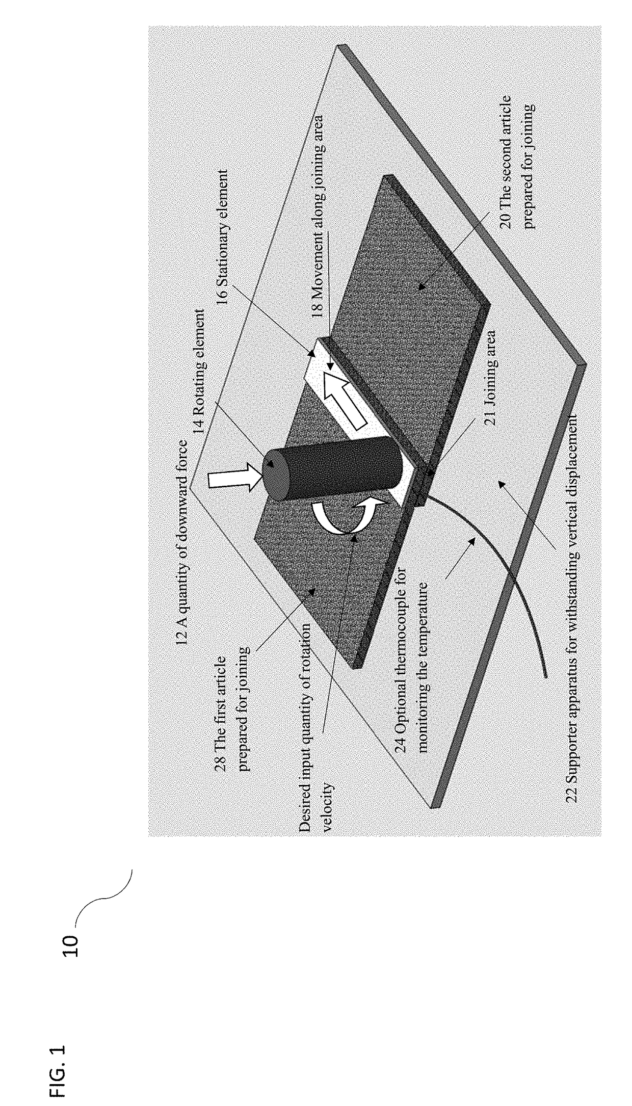
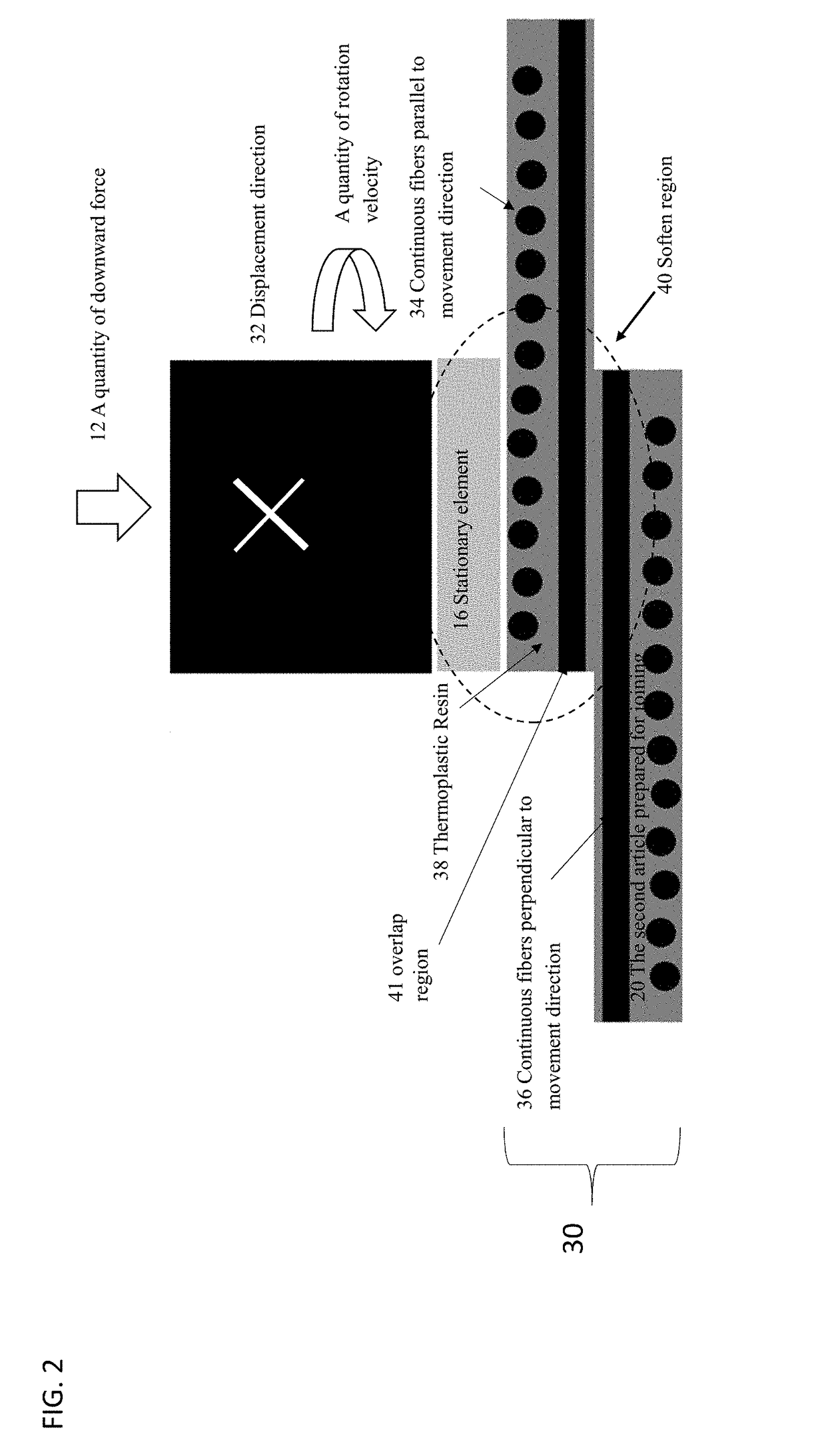
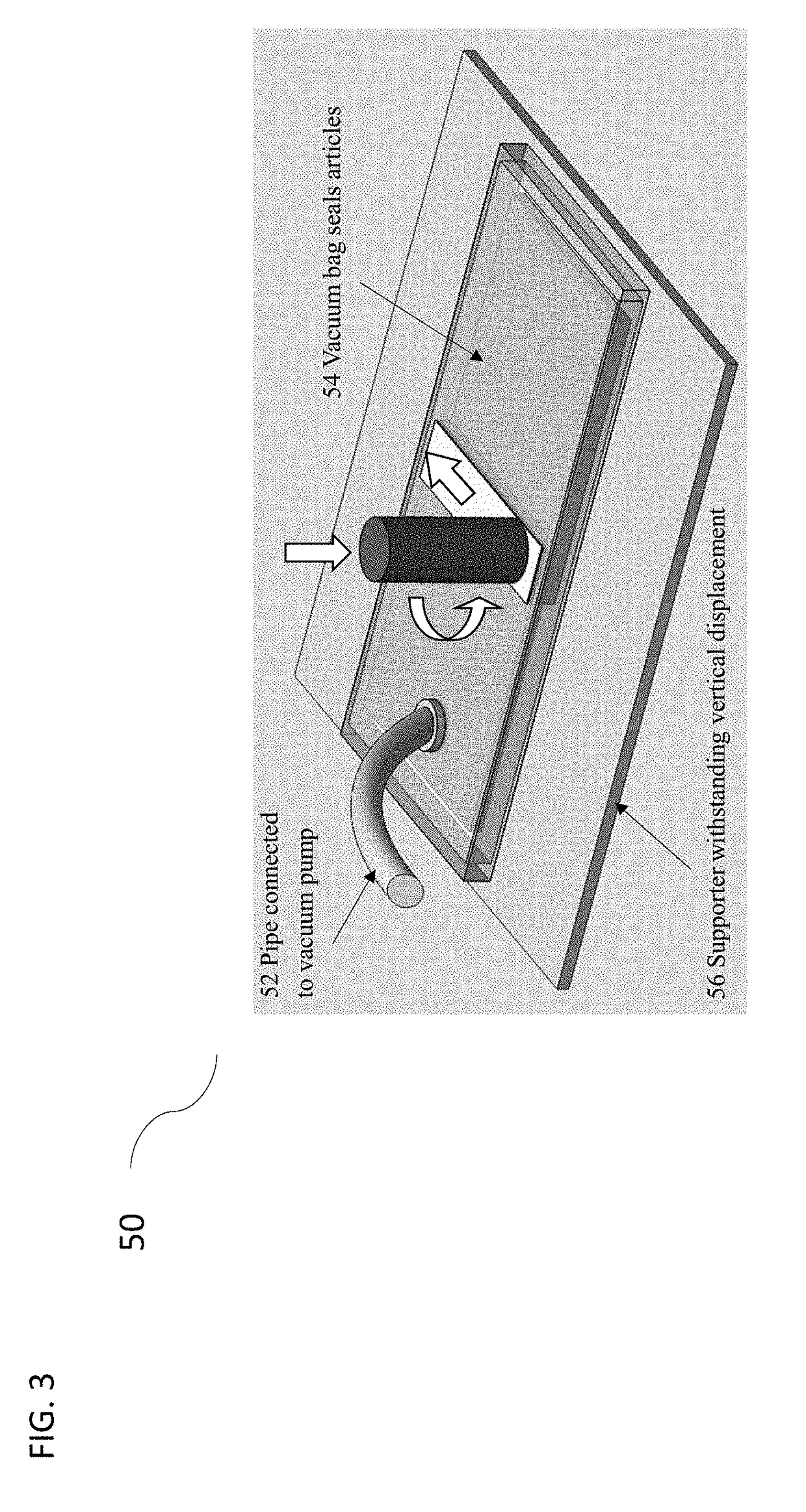
The present invention provides a new method and apparatus for joining fiber reinforced thermoplastics using external heat to soften the resin. This method can create strong and robust joining between fiber reinforced thermoplastics and can also form a strong mechanical keying in joining fiber reinforced thermoplastics to metal. The joining process can be carried out under vacuum atmosphere for better performance. The apparatus includes a rotating pin driven by an actuator and multiple actuators to provide versatility in application conditions. The apparatus is easy to use, install, light weight, inexpensive, and efficient.

Problems solved by technology

Once shaped and cured, fiber reinforced thermosets may not be reheated and reshaped.
The application of fiber reinforced polymer in the automotive industry is still limited to the relatively high cost of the fiber reinforced polymer.
In this case, the inevitable drilling process introduces stress concentration in components, which process also breaks the reinforced fiber of the region adjacent to drilled holes.
As a consequence, the service life and safety performance of the joint structure is deteriorated by employing mechanical fastening.
In addition, the employment of fasteners will add extra cost and weight to the structural components.
Since fiber reinforced thermoplastics are usually served in high temperature applications, therefore conventional adhesives, such as epoxy based adhesive, are not suitable for joining fiber reinforced thermoplastics.
In addition, adhesive bonding requires complicated surface preparation prior to joining.
The joining processing time, i.e. curing of the adhesive, is quite long and the cost of adhesive is additional to the cost of the structural components.
Since this process integrates joining process with consolidation process which requires sophisticated and expensive equipment with substantive cost of energy and time, the co-consolidation process is more suitable in fabricating a fiber reinforced thermoplastic component with designed joint features, but not as a fast and economic process to join fiber reinforced thermoplastic component or metal component to an existing fiber reinforced thermoplastic component.
However, most of the welding technique requires elaborate and specific equipment and a specific design of the joined components.
In addition, some welding techniques are not capable to accurately control the welding parameters, which further results in inconsistent welding quality.

Method used


Image

  • System and Apparatus for Fiber Reinforced Thermoplastics Joiner
  • System and Apparatus for Fiber Reinforced Thermoplastics Joiner
  • System and Apparatus for Fiber Reinforced Thermoplastics Joiner

Examples


second embodiment

[0048]FIG. 8, illustrates a side view of a mechanical schematic of the apparatus which is used for joining a metal stiffener feature to fiber reinforced thermoplastic aero structures 110. At least one Metal stiffener 114 are joined with fiber reinforced thermoplastic aero structures 112. In this embodiment, the stationary element 16 is optional, depending on the property of metal stiffeners 114 and joining parameters.

third embodiment

[0049]FIG. 9, illustrates a side view of a mechanical schematic of the apparatus which is used for joining fiber reinforced thermoplastic to reinforced metal automotive structures 120, increasing the stiffness and strength of that structure. Fiber reinforced thermoplastic 122 is joined with the metal automotive structure 124 as the second article. The metal surface can be treated to facilitate the joining performance between metal and thermoplastic composite.

[0050]The stationary element 16 should be temporarily fixated or restrained, and the release agent 106 is suggested to be inserted between the stationary element 16 and the fiber reinforced thermoplastic 124 to facilitate the removal of the stationary element 16. The rotation velocity of the rotating element 14 should be elaborated to soften the fiber reinforced thermoplastic 122. An optional supporter of metal structure 126 may be required to withstand the downward force which may deform the metal structure.

fourth embodiment

[0051]FIG. 10 illustrates a side view of a mechanical schematic of the apparatus which is used for joining fiber reinforced thermoplastic to repair damaged metal civil structures 130. In this embodiment the damaged metal structure 134 is the second article, while the first article is the fiber reinforced thermoplastic 122 employed for repairing. The fiber reinforced thermoplastic 122 is softened, and the thermoplastic resin 136 in the first article will flow into the crack 132 and the undamaged metal surface will also bond with the fiber reinforced thermoplastic 122. The damaged metal structure 134 is thus reinforced by the joined fiber reinforced thermoplastic 122. In this case supporter may not be necessary if the metal structure 134 can withstand downward force with negligible displacement. The stationary element 16 should be temporarily fixated, and release agent 106 is suggested to be inserted between the stationary element 16 and the fiber reinforced thermoplastic 122 to facil...


PUM

PropertyMeasurementUnit
Forceaaaaaaaaaa
Areaaaaaaaaaaa
Velocityaaaaaaaaaa

Abstract

A system for, and method of making and repairing a fiber-reinforced component including bonding a first thermoplastic matrix possessing reinforcing fibers distributed therein to a second composite member possessing a thermoplastic matrix with reinforcing fibers distributed therein; and metals and more particularly a method and apparatuses for joining fiber reinforced thermoplastics utilizing a combination of heat, force and rotational force.

Description

CROSS REFERENCE TO RELATED APPLICATION[0001]This application takes priority from and claims the benefit of U.S. Provisional Application Ser. No. 62 / 513,002, filed on May 31, 2017, the contents of which are herein incorporated by reference.BACKGROUND OF THE INVENTIONField of the Invention[0002]The present system pertains to apparatuses and methods for joining fiber reinforced thermoplastics to fiber reinforced thermoplastics and metals and more particularly a method and apparatuses for joining fiber reinforced thermoplastics using heat through friction.Description of the Related Art[0003]Lightweight structures show remarkable advantages in various industrial sectors and products. A prevalent approach to reducing the weight of structural components is to involve fiber reinforced polymer material into product design and fabrication. Fiber reinforced polymer consists of high strength reinforcement fiber embedded in a polymer matrix which can be either thermoset polymer or thermoplastic ...

Claims


Application Information

Patent Timeline
IPC IPC(8): B29C65/06B29C65/00B29C65/78
CPCB29C65/0681B29C66/1122B29C66/71B29C66/72141B29C65/7847B29C66/863B29C66/74283B29C66/836B29C65/645B29C66/00145B29C66/112B29C66/131B29C66/43B29C66/472B29C66/524B29C66/532B29C66/5326B29C66/73921B29C66/742B29C66/81455B29C66/8322B29C66/91212B29C66/91221B29C66/9241B29C66/93451B29L2031/3082B29C73/10B29C73/30B29C37/0067B25J11/00
Inventor SU, YIBO
Owner SU YIBO
Why Eureka
Eureka Blog
Learn More