
Low Electric Fan-Type Power Generating Device with Low Energy Consumption

a power generating device and fan-type technology, applied in the direction of machines/engines, mechanical equipment, liquid fuel engines, etc., can solve the problems of direct power loss, inability to use anytime and anywhere, and inability to recycle and reuse mechanical energy generated by the motor, etc., to prolong the service time of the chargeable battery and low energy consumption

Active Publication Date: 2018-11-29
CHENG CHUN YING +1
View PDF0 Cites 2 Cited by
  • Summary
  • Abstract
  • Description
  • Claims
  • Application Information

AI Technical Summary

Benefits of technology

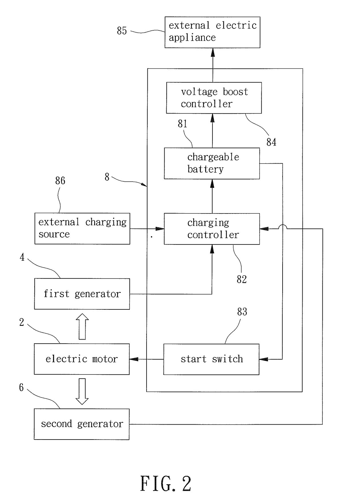
The patent is for an electric fan-based power generating device that produces wind energy from the rotation of three fans. The first and second fans use the wind energy to drive a third fan, which in turn powers a first generator to generate electricity. The second fan also powers a fourth fan, which generates electricity for a second generator. The chargeable battery recycling the released energy to support the electric motor and maintain sustained operation. Additionally, the patent aims to increase the windage area and starting speed by designing the diameter of the third and fourth fans to be larger than the first fan. Overall, this invention allows for energy efficient and portable power generation in any location.

Problems solved by technology

However, these fans using motors must be powered by the main power and, thus, cannot be used anytime and anywhere.
Furthermore, the mechanical energy generated by the motor is not recycled and reused.
Namely, the mechanical energy is direct power loss.
The cumulative loss of energy is considerable.
Thus, it is an important issue to persons in this field.

Method used


Image

  • Low Electric Fan-Type Power Generating Device with Low Energy Consumption
  • Low Electric Fan-Type Power Generating Device with Low Energy Consumption
  • Low Electric Fan-Type Power Generating Device with Low Energy Consumption

Examples


Embodiment Construction

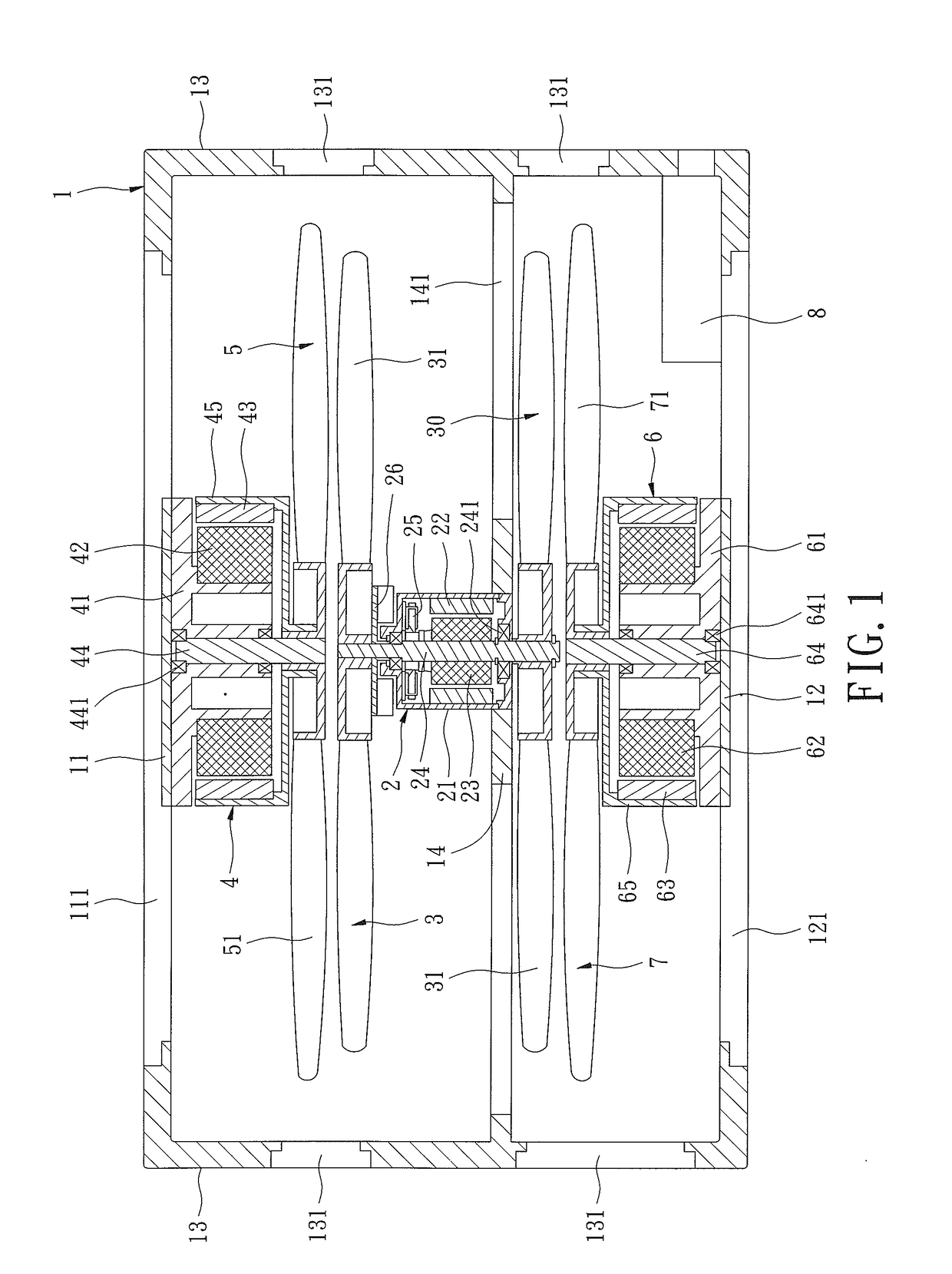
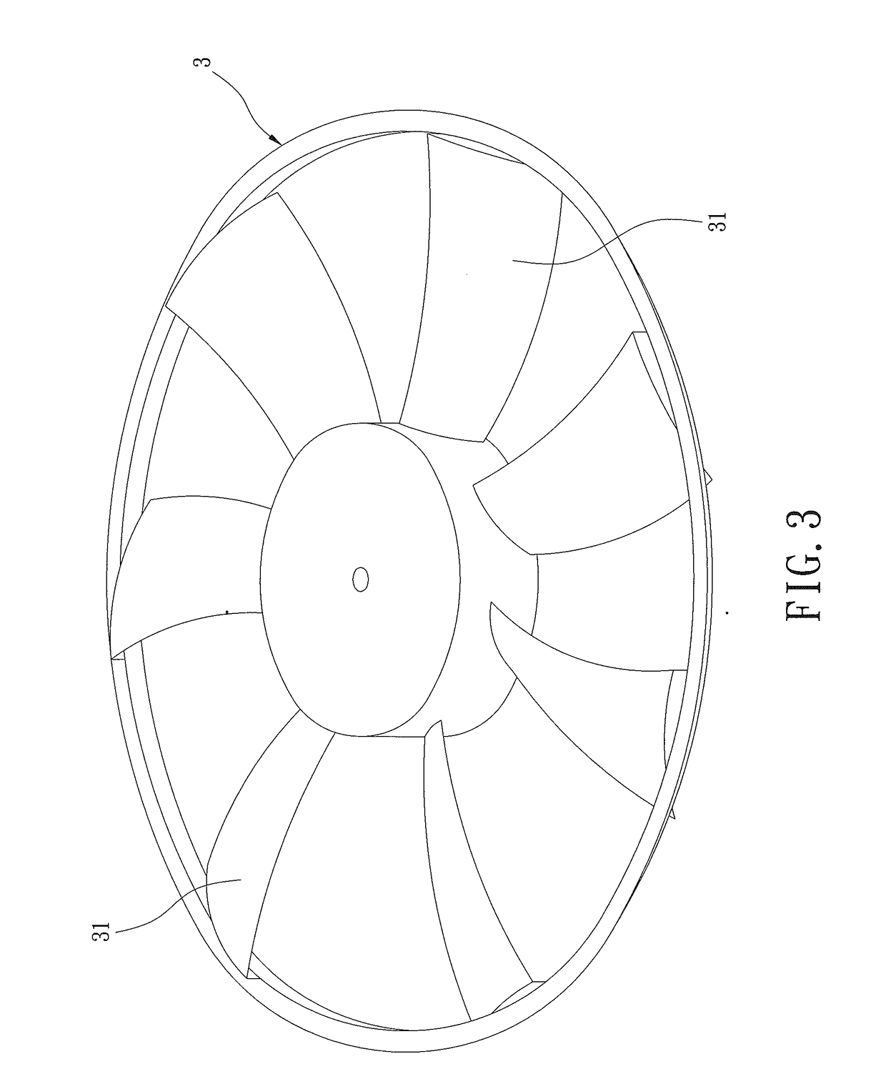
[0027]With reference to FIGS. 1-3, an electric fan-type power generating device with low energy consumption of a first example according to the present invention includes a housing 1 having a first sidewall 11, a second sidewall 12 opposite to the first sidewall 11, and a peripheral wall 13 interconnected between the first sidewall 11 and the second sidewall 12. The housing 1 further includes a first support 14 extending parallel to and located between the first sidewall 11 and the second sidewall 12. Vents 111, 121, 131, and 141 are respectively defined in the first sidewall 11, the second sidewall 12, the peripheral wall 13, and the first support 14.

[0028]An electric motor 2 is mounted in the housing 1 and includes a first stator 22 and a first rotor 23 concentric to the first stator 22. The electric motor 2 further includes an electrically connected carbon brush 25. A first shaft 24 extends through a central portion of the first rotor 23 and is coupled to the first rotor 23. The ...


PUM


Abstract

An electric fan-type power generating device includes a housing receiving an electric motor that is supplied electricity from a chargeable battery to drive a first fan and a second fan to rotate at high speeds to thereby generate wind power close to a third fan mounted to a first generator. The first fan uses the wind power to drive the third fan in the housing. The third fan drives the first generator to generate electricity that is supplied to the chargeable battery. The second fan uses the wind power in the housing to drive a fourth fan to rotate. The fourth fan drives the second generator to generate electricity that is supplied to the chargeable battery. The chargeable battery recycles the electricity that supports operation of the electric motor for generating wind power. Furthermore, the wind power drives the first and second generators to continue generating electricity.

Description

BACKGROUND OF THE INVENTION[0001]The present invention relates to a power generating device and, more particularly, to an electric fan-type power generating device with low energy consumption.[0002]Various fans use main power as the power source for driving a motor to rotate fan blades. The air behind the fan blades is driven forward to generate wind power making air flow.[0003]However, these fans using motors must be powered by the main power and, thus, cannot be used anytime and anywhere. Furthermore, the mechanical energy generated by the motor is not recycled and reused. Namely, the mechanical energy is direct power loss. The cumulative loss of energy is considerable. Thus, it is an important issue to persons in this field.BRIEF SUMMARY OF THE INVENTION[0004]The primary objective of the present invention is to provide an electric fan-type power generating device with low energy consumption using an electric fan to drive a first fan and a second fan to rotate at high speeds to th...

Claims


Application Information

Patent Timeline
IPC IPC(8): H02K47/14F04D19/00F04D25/06F04D29/32
CPCH02K47/14F04D19/002Y10S74/09F04D29/325H02K53/00F04D25/0673F04D25/024F04D19/007F04D25/166
Inventor CHENG, CHUN-YINGCHENG, JUNG-CHIEH
Owner CHENG CHUN YING
Learn More