Antenna structure

a technology of antenna structure and antenna body, which is applied in the direction of antennas, antenna supports/mountings, electrical appliances, etc., can solve the problems of difficult manufacturing of antenna structures, difficult to control the impedance matching of lte antenna structures, and difficult to manufacture antenna structures, etc., to achieve lower antenna structure height, shorter length, and denser structure

Active Publication Date: 2018-11-29
TAOGLAS GROUP HLDG LTD
View PDF3 Cites 8 Cited by
  • Summary
  • Abstract
  • Description
  • Claims
  • Application Information

AI Technical Summary

Benefits of technology

[0004]Therefore, the main object of the present invention is that the present invention re-designs the LTE antenna structure. Utilizing vertical segments in different lengths designs the multi-trace planar inverted-F antenna. Besides obtaining the best bandwidth covering the full band, the height of the antenna structure is lower, the length is shorter and the structure is denser. The impedance matching of the antenna structure can be controlled by the designer. No external matching element is required. With the multi-trace and grounded-short-circuit design of the antenna structure, the better resonance in the LTE full band is obtained.

Problems solved by technology

Although the LTE antenna structures mentioned above can achieve the predetermined communication effect, the volumes of the LTE antenna structures are large, the impedance matching of the LTE antenna structures themselves are not controlled easily, and the external matching elements are required to adjust the impedance matching, so that manufacturing the antenna structures is difficult and not easy.

Method used


Image

  • Antenna structure
  • Antenna structure
  • Antenna structure

Examples


Embodiment Construction

[0025]Now please refer to following detailed description and figures for the technical content of the present invention:

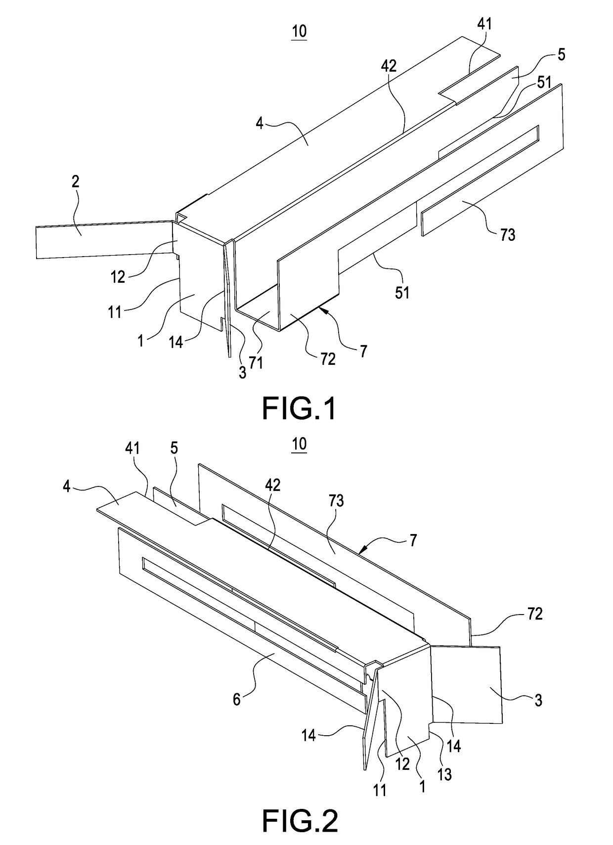
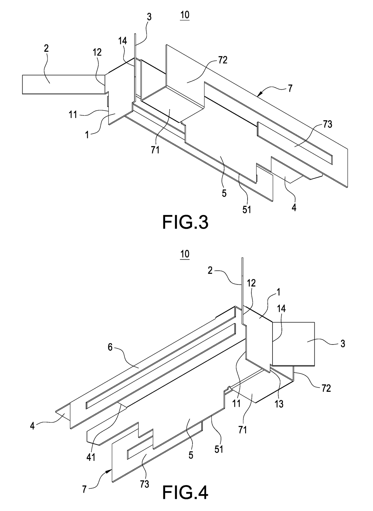
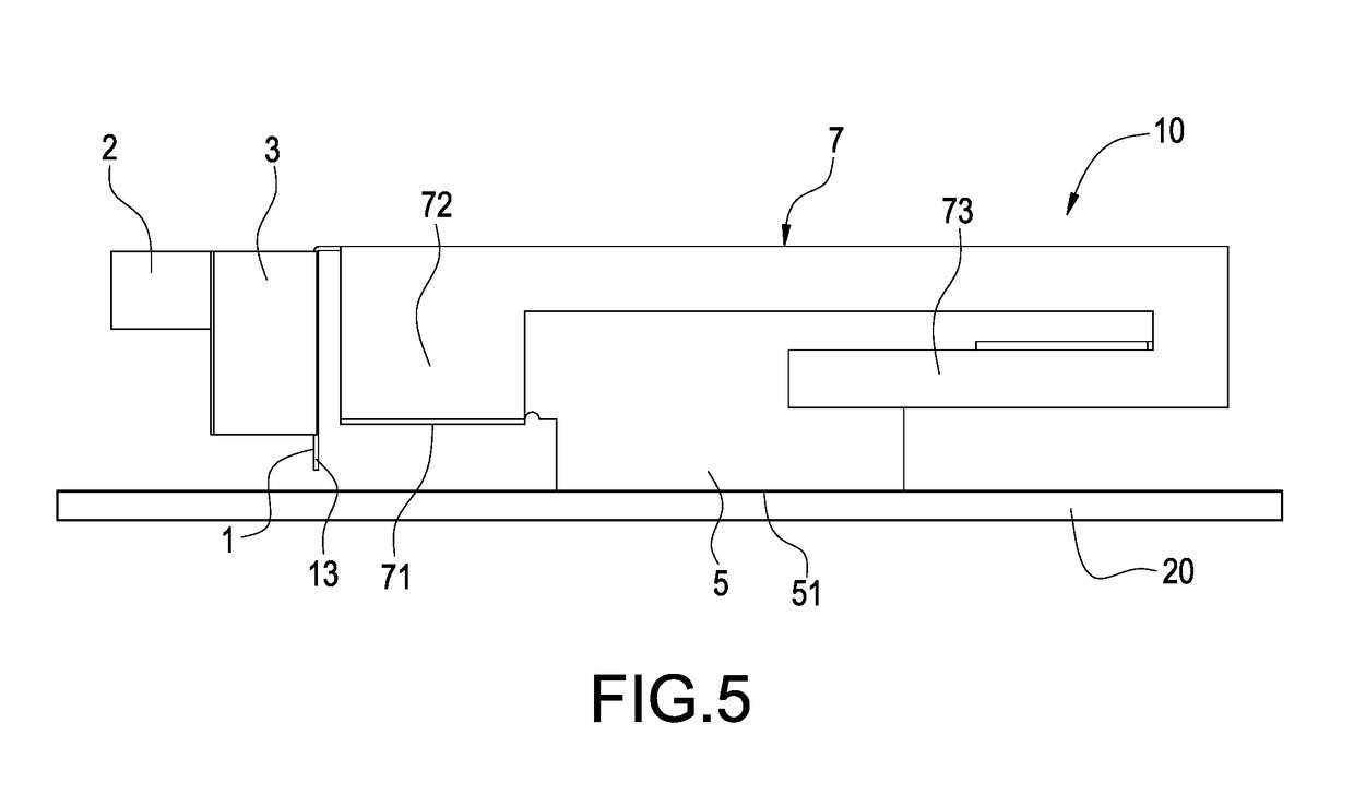
[0026]FIG. 1 shows a schematic diagram of the front view of the antenna structure of the present invention. FIG. 2 shows a schematic diagram of the back view of the antenna structure of the present invention. FIG. 3 shows a schematic diagram of the front looking-up view of the antenna structure of the present invention. FIG. 4 shows a schematic diagram of the back looking-up view of the antenna structure of the present invention. As shown in FIGS. 1˜4, an antenna structure 10 of the present invention is manufactured with a metal sheet (or metal sheets) pressed and bended. The antenna structure 10 comprises an antenna feed-in element 1, a first antenna trace element 2, a second antenna trace element 3, a supporting element 4, a grounded-short-circuit element 5, a third antenna trace element 6 and a fourth antenna trace element 7. The antenna structure 10 is applied ...


PUM


Abstract

An antenna structure (10) includes an antenna feed-in element (1), a first antenna trace element (2), a second antenna trace element (3), a supporting element (4), a grounded-short-circuit element (5), a third antenna trace element (6) and a fourth antenna trace element (7). The first antenna trace element (2), the second antenna trace element (3), the third antenna trace element (6) and the fourth antenna trace element (7) which have vertical segments in different lengths form a multi-trace planar inverted-F antenna to obtain the best bandwidth covering the full band, so that the height of the antenna structure (10) is lower, the length is shorter and the structure is denser. The impedance matching of the antenna structure (10) is controlled easily. No external matching element is required. With the multi-trace and grounded-short-circuit design of the antenna structure (10), the better resonance in the LTE full band is obtained.

Description

BACKGROUND OF THE INVENTIONField of the Invention[0001]The present invention relates to an antenna, and especially relates to a planar inverted-F antenna (PIFA) structure having the ultra-wide band long term evolution (LTE) technology.Description of the Related Art[0002]The long term evolution (LTE) technology is a high speed wireless communication standard for the mobile phone and data terminal in the telecommunication. The standard is based on the previous GSM / EDGE and UMTS / HSPA network technology, and uses the modulation technology to increase the network capacity and speed.[0003]Currently, there are many types of LTE antennas. Some LTE antenna structures are manufactured with metal sheets which are pressed (or punched) and then bended. Some LTE antenna structures are manufactured by printing the pattern layer of the antenna on the circuit board directly, and then the antenna pattern is manufactured by the etching technology. Moreover, some LTE antenna structures are manufactured...

Claims


Application Information

Patent Timeline
Patent Type & Authority Applications(United States)
IPC IPC(8): H01Q9/04H01Q1/24
CPCH01Q9/0421H01Q1/243H01Q9/045H01Q9/42H01Q5/371
Inventor QUINLAN, RONANYANG, WEN-CHIEHCHEN, MING-WEI
Owner TAOGLAS GROUP HLDG LTD
Why Eureka
Try Eureka