
Continuous Compression Wire Spring Polishing Apparatus Configured to Easily Replace Two Parallel and Opposite Grindstones

Active Publication Date: 2018-11-29
DAEWON APPLIED ENG CO
View PDF18 Cites 4 Cited by
  • Summary
  • Abstract
  • Description
  • Claims
  • Application Information

AI Technical Summary

Benefits of technology

The patent describes a continuous compression wire spring polishing apparatus that can efficiently polish end surfaces of compression wire springs. The apparatus includes grinding units, hinge shafts, and an upper guide to prevent the compression wire spring from springing out. The grindstone of each grinding unit can be easily replaced by using a pneumatic cylinder to turn the grindstone fixing shaft to a horizontal or vertical state. The horizontal state can be precisely adjusted to ensure correct polishing of the end surfaces of the compression wire springs. The technical effects of this invention include easy replacement of grindstone, efficient placement of grindstone, and precise adjustment of the horizontal state for polishing the end surfaces of compression wire springs.

Problems solved by technology

However, in the case where a polishing grindstone of the grinding unit is to be replaced, the replacement work space is too narrow so that the periodic replacement of polishing grindstones is not easy and the replacement work time is increased, which deteriorates facility utilization efficiency.
However, there are problems in that since the assembly device has a complicated structure since the assembly device is configured to necessarily use a V-belt and a speed reducer and in that the structure of tilter rotation device cannot be applied to a grinding unit directly connected to a motor in a continuous compression wire spring polishing apparatus.

Method used


Image

  • Continuous Compression Wire Spring Polishing Apparatus Configured to Easily Replace Two Parallel and Opposite Grindstones
  • Continuous Compression Wire Spring Polishing Apparatus Configured to Easily Replace Two Parallel and Opposite Grindstones
  • Continuous Compression Wire Spring Polishing Apparatus Configured to Easily Replace Two Parallel and Opposite Grindstones

Examples


Embodiment Construction

[0021]Hereinafter, embodiments of the present disclosure will be described with reference to the accompanying drawings. Descriptions will be made in detail with reference to the portions necessary for understanding the operations and actions according to the present disclosure. While the embodiments of the present disclosure have been described, a description for technical features, which are well known in the technical field to which the present disclosure belongs and are not directly related to the present disclosure, will be omitted. This is to transmit the gist of the present disclosure more clearly without obscuring the gist of the present disclosure by omitting unnecessary descriptions.

[0022]In describing the constituent elements of the present disclosure, the constituent elements of the same names may be denoted by different reference numerals in some drawings, or may be denoted by the same reference numerals even in different drawings. However, even in such a case, it does n...


PUM


Abstract

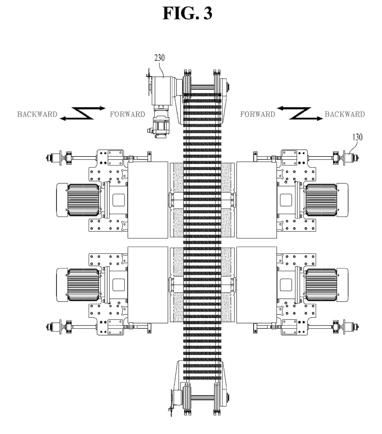
The present disclosure relates to a contiguous compression wire sprang polishing apparatus that continuously polishes end surfaces of compression wise springs (10) by upper and lower chain conveyers 100 and 200 and grinding units 300. The apparatus includes: two gaming units (300) each having a grindstone (350) to which rotational force of a motor (240) is transmitted through a gear box (260), the motor (240) having a rotary shaft being located above a central axis of the grindstone (350), and the two grinding units (300) being installed to be parallel and opposite to each other at opposite sides of a compression wire spring (10) fixed to the continuous compression wire spring polishing apparatus so as to polish opposite end surfaces of the compression wire spring (10); two hinge shafts (140), which are fixed at positions, which are spaced apart from grindstones in the lowest surface of the grinding units (300) by a predetermined distance, and which are inserted into and coupled to bearings, which are fixed to a body of the polishing apparatus; an upper guide (225) configured to prevent the compression wire spring (10) from springing out and a rod end fixing shaft (150) fixed to an end of the cylinder rod (170) of the pneumatic cylinder (180) inserted into and coupled to a bearing fixed at a position between the grindstone rotation shaft and the hinge shaft (140) in each of the grinding units (300). The grindstone rotation shaft of each of the grinding units (300) is turned into the vertical state or the horizontal state according to the forward and backward movements of the pneumatic cylinder (180), so that the two grindstones (350) of the grinding units (300), which are mounted to be parallel and opposite to each other, can be easily replaced.

Description

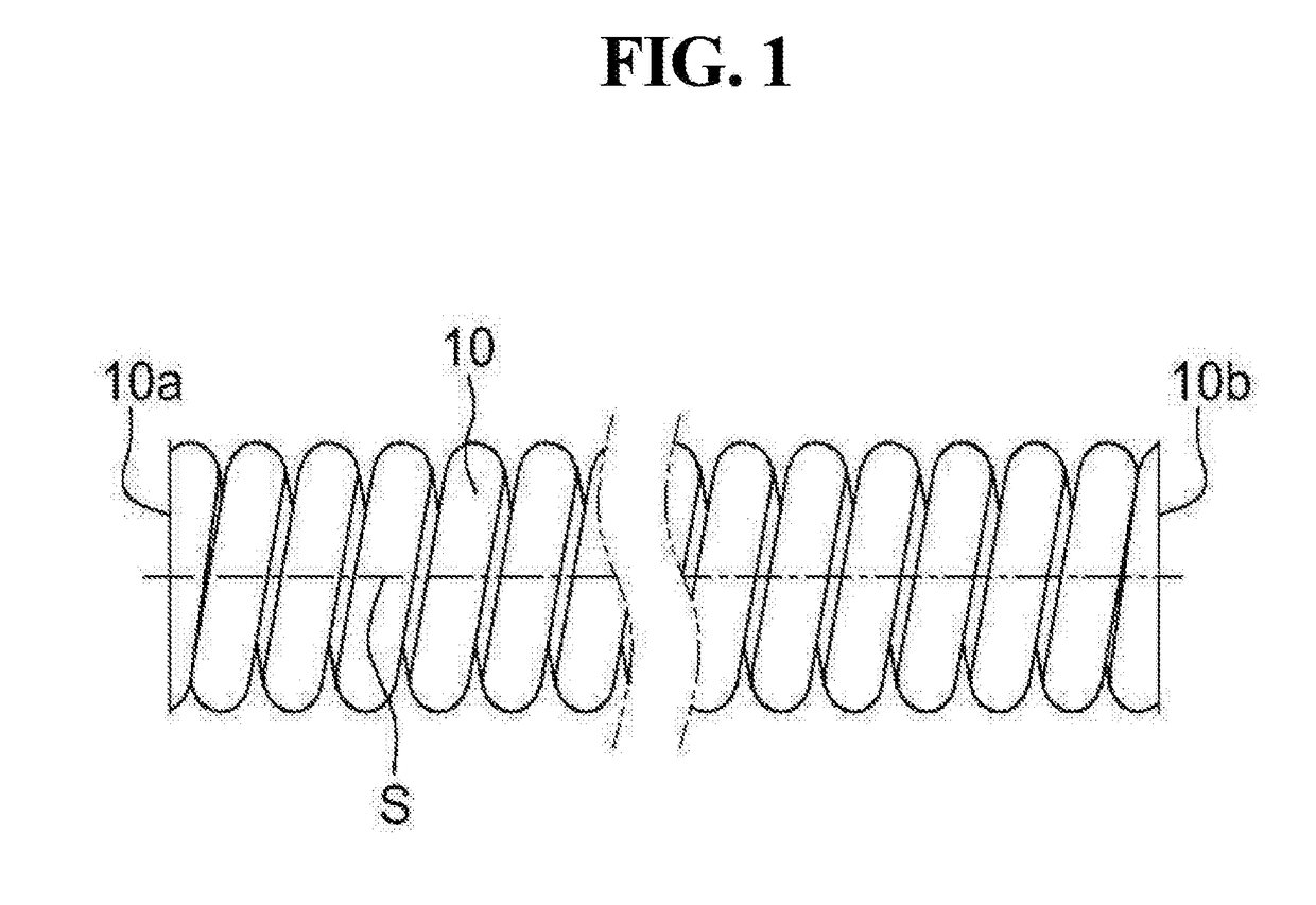
BACKGROUND Of THE INVENTIONField of the Invention[0001]The present disclosure relates to an apparatus for polishing both end seat surfaces of compression wire springs by attaching the compression wire springs to a chain conveyor, in which in order to easily replace a grindstone, a grindstone rotation shaft is rotated using a pneumatic apparatus, the grindstone is replaced to a state in which the grindstone rotation shaft is vertical, and the compression wire springs are polished in the state in which the grindstone rotation shaft is horizontal.Description of the Art[0002]FIG. 1 illustrates a structure of an ordinary compression wire spring, the end surfaces of which are polished. Generally, compression wire springs 10 are subjected to a so-called seat surface polishing process such that the opposite end surfaces 10a and 10b of a cylindrical shape, which is formed by spirally winding a wire material-type spring material, can be placed on a plane orthogonal to a spring axis S.[0003]Th...

Claims


Application Information

Patent Timeline
IPC IPC(8): B24B7/16B24B7/06B24B47/12
CPCB24B7/167B24B7/06B24B47/12B24B7/17B24B41/047B24B27/0076B24B45/006B24B7/10B24B45/003B24B47/14B24B47/10
Inventor CHUNG, CHAN-KI
Owner DAEWON APPLIED ENG CO
Learn More