
Manifold

a manifold and internal combustion engine technology, applied in the direction of exhaust treatment, gas passages, silting apparatus, etc., can solve the problems of adversely affecting the resonance behavior, and achieve the effect of simple and economical fabrication methods, acoustic disadvantages of sheet metal

Active Publication Date: 2018-11-22
TENNECO
View PDF9 Cites 0 Cited by
  • Summary
  • Abstract
  • Description
  • Claims
  • Application Information

AI Technical Summary

Benefits of technology

The patent describes an improved design for air gap insulated manifolds in engines, which results in a more harmonious sound compared to existing manifold systems. The design takes into account the distance between the inlet and outlet openings, and the sonic behavior is greatly affected by changes in this distance. By increasing the distance between the openings, the sonic properties improve. The design also integrates the outlet openings into a load-bearing structural part between the engine block and turbocharger, providing additional benefits.

Problems solved by technology

In particular, it has been found that reflection surfaces which are aligned perpendicularly to the flow direction adversely affect the resonance behavior, which is why the outer air gap insulated manifold is bent in its geometry from its inlet opening to the outlet opening, said geometry deviating from that of the inner air gap insulated manifold.

Method used


Image

  • Manifold
  • Manifold
  • Manifold

Examples


Embodiment Construction

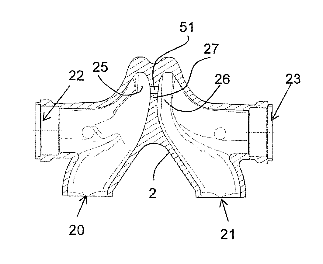
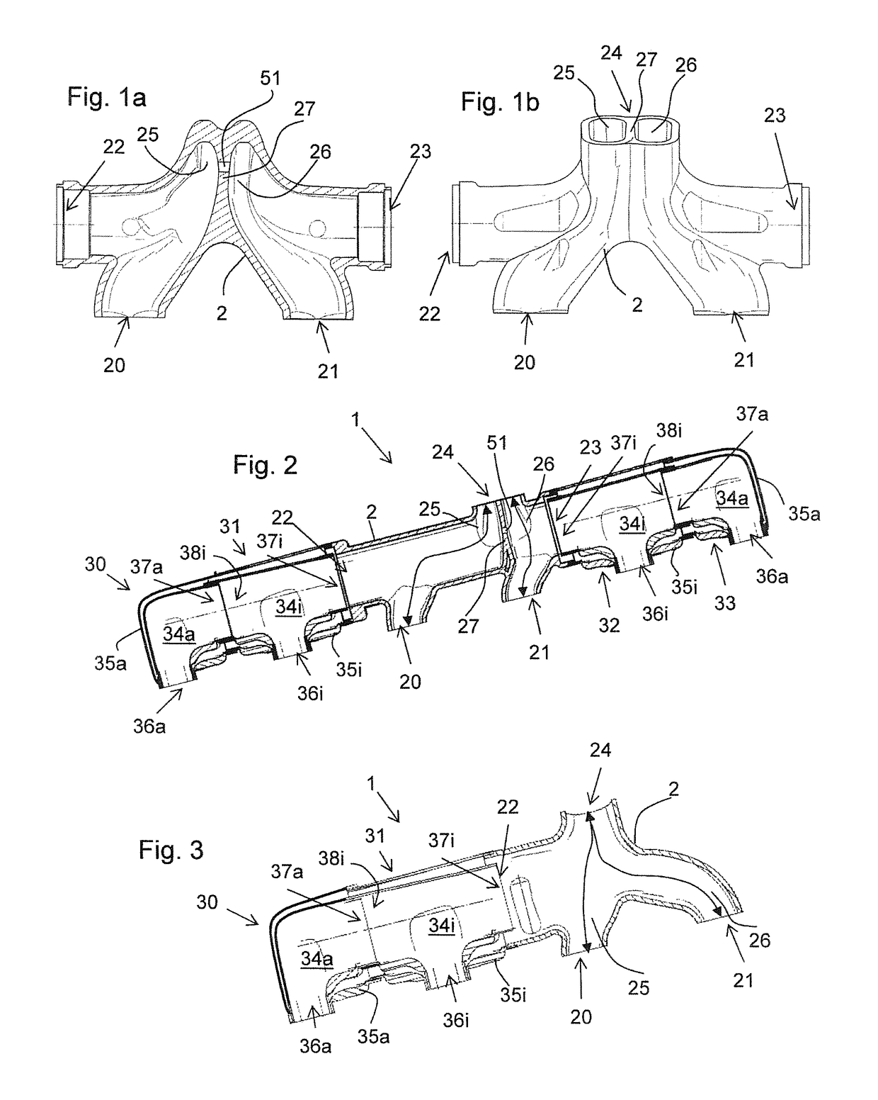
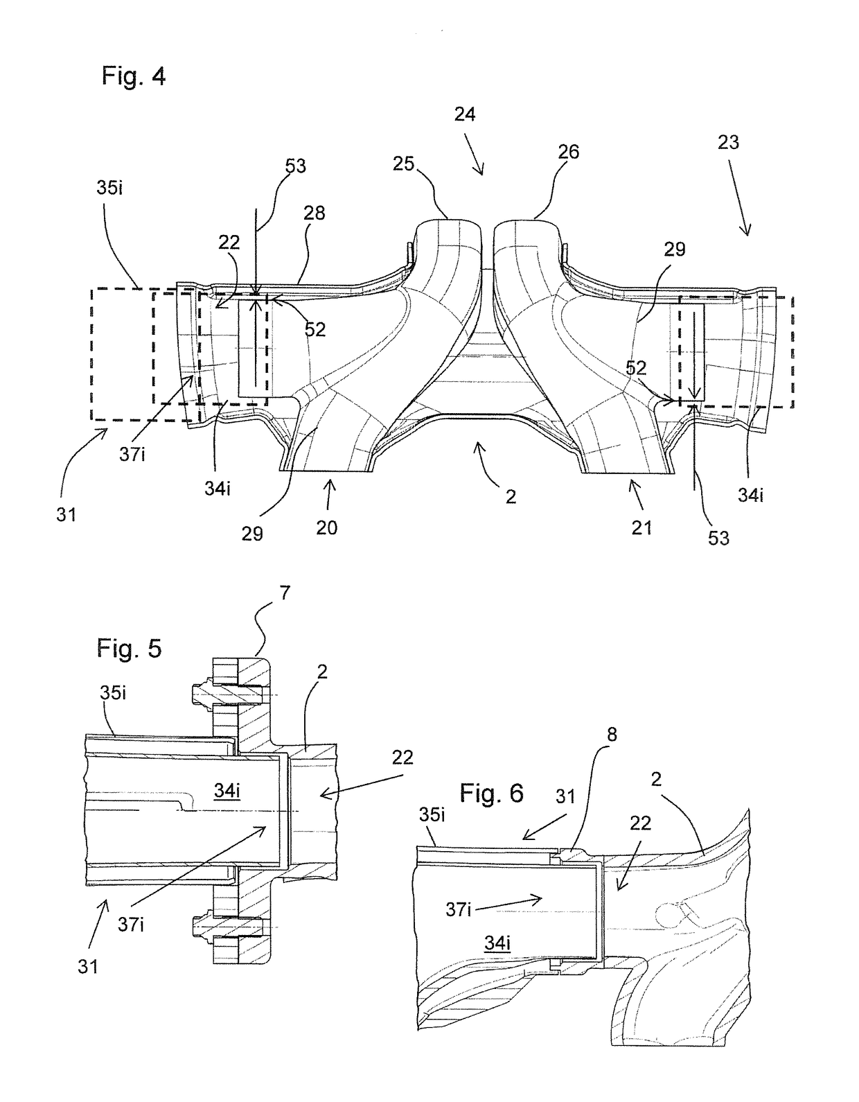
[0043]According to all of the embodiment examples a housing 2 is provided, having two inlet openings 20, 21 for connecting the housing 2 to outlets (not represented) of an internal combustion engine as well as one to two connection openings 22, 23 for connecting one air gap insulated manifold 30-31 each. Within the context of the cylinder sequence of an internal combustion engine having inner and outer cylinders, the “inner” air gap insulated manifolds 31, 32 in each case are arranged between the housing 2 and an outer air gap insulated manifold 30, 33, and the “outer” air gap insulated manifolds 30, 33 are arranged opposite the housing 2 on the respective inner air gap insulated manifold 31, 32.

[0044]FIG. 1a shows a sectional view of a housing 2 configured as a collecting manifold with flow ducts 25, 26 being in interaction. The housing 2 is formed from a gray cast iron and as well as the two inlet openings 20, 21 for connecting the housing 2 to outlets (not represented) of an inte...


PUM


Abstract

A manifold system for an internal combustion engine, having a housing, which is designed as a collecting manifold and which has two inlet openings and an outlet opening for the flow connection of two outlets of an internal combustion engine to an exhaust system and at most two connection openings provided on the housing for connecting a double-shell inner air-gap-insulated manifold. An exhaust system is developed in such a way that, at the same time, the tone of the exhaust gas noise and thus of the exhaust system is optimized over a plurality of important rotational speed ranges of the internal combustion engine by a modular assembly. For this purpose, at least one separate inner air-gap-insulated manifold having a connection opening, an inlet opening, and an outlet opening is provided, which is connected to the housing by the outlet opening, and at least one separate outer air-gap-insulated manifold having an inlet opening and an outlet opening is connected to the connection opening of the inner air-gap-insulated manifold. All air-gap-insulated manifolds are completely formed of sheet metal, and each air-gap-insulated manifold has a separate one- or multi-part inner shell and a one- or multi-part separate outer shell. All inner air-gap-insulated manifolds are structurally or geometrically identical and all outer air-gap-insulated manifolds are structurally or geometrically identical, wherein the inner air-gap-insulated manifolds are not structurally identical and not geometrically identical to the outer air-gap-insulated manifolds.

Description

FIELD OF THE INVENTION[0001]The invention relates to a manifold system for an internal combustion engine, comprising a housing configured as a collecting manifold, which housing has two inlet openings and an outlet opening for fluidically connecting two outlets of an internal combustion engine to an exhaust gas system. A maximum of two connection openings are located at the housing for connecting a double-shell inner air gap insulated manifold.BACKGROUND OF THE INVENTION[0002]The term ‘air gap insulated manifold’ is used to describe air gap insulated manifolds having an inner shell and an outer shell, which can be installed individually as a separate component. Such a separate air gap insulated manifold is always only assigned to an outlet opening on the engine side and does not form a collecting manifold, which combines a plurality of outlet openings on the engine side.[0003]Air gap insulated manifolds which are connected in flow direction to the housing formed as a collecting mani...

Claims


Application Information

Patent Timeline
Patent Type & Authority Applications(United States)
IPC IPC(8): F01N13/10F01N13/14F02B37/02F01N1/02F01N13/18
CPCF01N13/107F01N13/102F01N13/143F02B37/02F01N1/02F01N13/1805F01N13/1861F01N13/1888F01N2470/28F01N13/10F01N13/1894F01N2260/10F01N2470/00Y02T10/12
Inventor KAUFFMANN, STEFFENGEMINN, MARKUSSTEIGERT, ANDREASROTH, MARGIT
Owner TENNECO
Learn More