
Substrate baking apparatus and baking operation mehod thereof

a baking apparatus and substation technology, applied in the direction of photosensitive material processing, electrical equipment, basic electric elements, etc., can solve the problems of affecting the drying efficiency of subsequent other to-be-dried objects, and the gas volatilized from volatile liquids cannot be completely exhausted, so as to achieve stable flow

Inactive Publication Date: 2018-11-15
HKC CORP LTD +1
View PDF0 Cites 5 Cited by
  • Summary
  • Abstract
  • Description
  • Claims
  • Application Information

AI Technical Summary

Benefits of technology

The patent application describes a device that can regulate and control the flow of air for different volatile materials. This device can be used in pre-drying oven processes for different materials. Its main benefits are that it allows for stable air flow and control over the flow of air, which can improve the processing of these materials.

Problems solved by technology

However, there are three disadvantages in drying in the first manner.
A first disadvantage is that if the to-be-dried object is taken out from an interior of the drying apparatus, an internal temperature abruptly decreases because a door is open and the to-be-dried object is in contact with external air, which, further, affects drying efficiency of subsequent other to-be-dried objects.
A second disadvantage is that poor design of internal air exhaust and intake of the drying apparatus causes air flow turbulence.
As a result, gases volatilized from volatile liquids cannot be completely exhausted successfully.
In addition, the air blower is not designed to supply air in a single direction, which, as a result, increases a possibility that when being in contact with a running machine such as a motor, volatile gases cause an electric arc or a spark, and further generate an explosion or fire.
A third disadvantage is that some volatile gases that cannot be exhausted successfully may corrode electrodes of a machine such as a motor, resulting in poor contact.
As a result, costs of use of the vacuum pumping manner are excessively high.

Method used


Image

  • Substrate baking apparatus and baking operation mehod thereof
  • Substrate baking apparatus and baking operation mehod thereof
  • Substrate baking apparatus and baking operation mehod thereof

Examples


Embodiment Construction

[0021]The following embodiments are described with reference to the accompanying drawings, and are examples of particular embodiments that may be implemented in this application. Directional terms mentioned in this application, for example, “above”, “below”, “front”, “back”, “left”, “right”, “inside”, “outside”, and “side surface”, are merely directions for referring to the accompanying drawings. Therefore, the used directional terms are intended for description and understanding other than limiting this application.

[0022]The accompanying drawings and the descriptions are considered to be essentially illustrative instead of being limitative. In the figures, units having similar structures are represented by using a same reference sign. In addition, for understanding and ease of description, the size and thickness of each component shown in the accompany drawings are randomly illustrated. No limitation is imposed in this application.

[0023]In the accompany drawings, for the purpose of...


PUM


Abstract

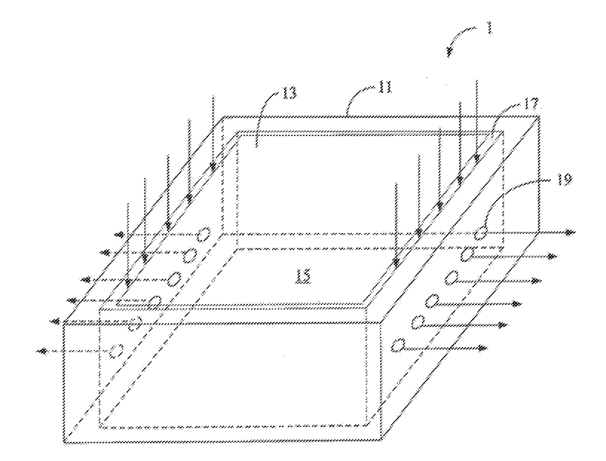
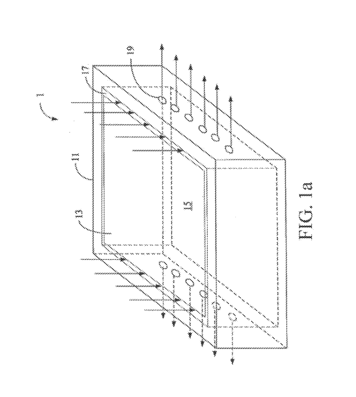
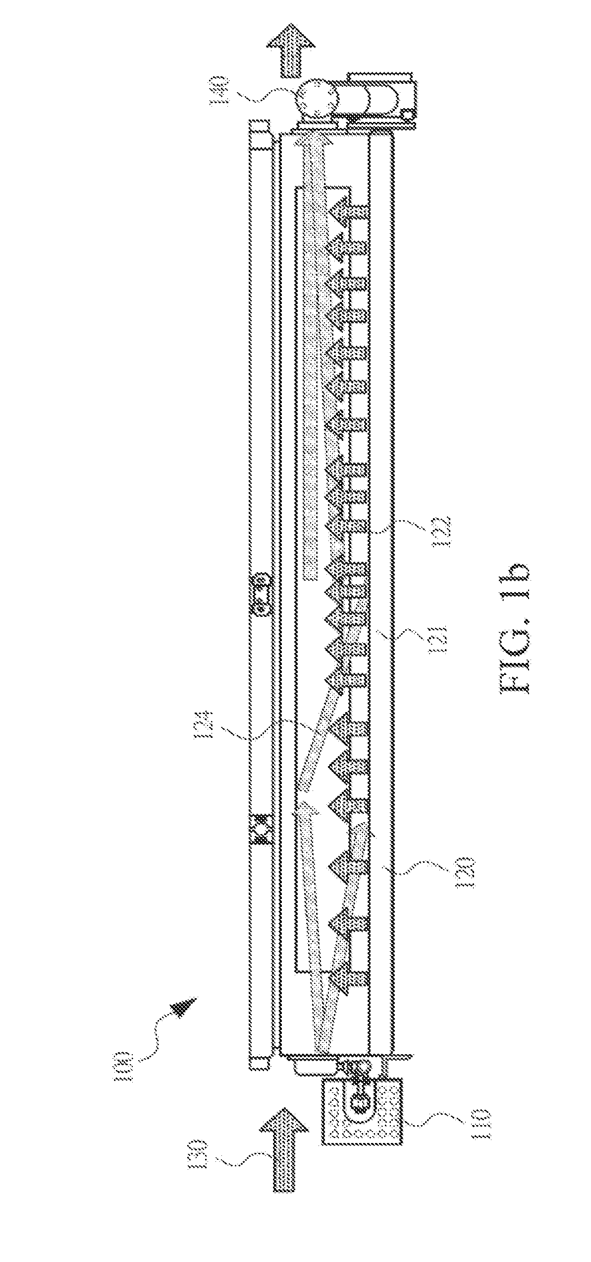
This application provides a substrate baking apparatus and a baking operation method. The apparatus includes: a ring-shaped bearer body, used to cover a substrate; a cover plate, disposed on the ring-shaped bearer body, which, together with the cover plate, defines a sealed chamber, where a surface of the substrate is located inside the sealed chamber; an air intake unit and an exhaust discharge unit, respectively disposed on an intake end and a discharge end of the sealed chamber; and an exhaust regulation air-extraction system, disposed on an upper part of the cover plate, communicated with the sealed chamber, and used to regulate and discharge evaporated gases of a great number of volatiles of the substrate.

Description

BACKGROUNDTechnical Field[0001]This application relates to a design for controlling stability flowage of an air flow, and in particular, to a substrate baking apparatus and a baking operation method thereof.Related Art[0002]A liquid crystal display panel is usually constituted by a color filter (CF) substrate, a thin film transistor array substrate (TFT array substrate), and a liquid crystal layer disposed between the two substrates. A working principle of the liquid crystal display panel is applying a drive voltage on the two glass substrates to control rotation of liquid crystal molecules of the liquid crystal layer, so as to refract light rays of a backlight module to generate an image. In a preliminary-stage process of a thin film transistor-liquid crystal display (TFT-LCD) and a color filter, after coating a photo-resist used for a product in a photo process, a content of a solvent of the photo-resist on a glass surface is relatively high, so that the product needs to be put in...

Claims


Application Information

Patent Timeline
IPC IPC(8): G03F7/40H01L21/67G03F7/38
CPCG03F7/40H01L21/67109G03F7/38
Inventor HUANG, CHUN-CHIN
Owner HKC CORP LTD
Learn More