
Applicator with Breakaway Cap

Active Publication Date: 2018-11-01
HARTZ MOUNTAIN
View PDF47 Cites 0 Cited by
  • Summary
  • Abstract
  • Description
  • Claims
  • Application Information

AI Technical Summary

Benefits of technology

The present invention is an applicator assembly with a one-piece design that reduces manufacturing costs and ensures the contents remain in an air-tight, sealed reservoir until the cap is separated from the body. The applicator includes a body and a cap that can be articulated, levered, pulled, or twisted to separate from the body. The cap includes a frangible portion to aid in separation and to minimize fragmentation at the breaking point between the neck and the projection when removing the cap. The frangible portion can extend inwardly from the outer surface of the projection or from the inner cavity of the neck. The applicator also includes a shroud with protrusions that extend about the outer periphery of the neck and form a recessed channel to aid in dispensing the contents when the neck is in direct contact with a surface.

Problems solved by technology

However, the designs of many existing applicators have several drawbacks.
For example, known applicators allow for potential leakage and / or contamination and / or evaporation of the contents stored within the housing of an applicator, do not allow for a direct application of the contents housed within the applicator at a desired contact site, and / or are cumbersome to use.
Additionally, many known applicator designs do not allow for all measured contents to be released from the housing.
For example, at least one cavity may be formed upon puncturing the housing to create an opening or unsealing an opening formed in the body of a housing of an applicator, which in turn can result in trapping fluid within the body of the housing.
When the applicator comes in contact, as is commonly the case, with a surface (e.g., the skin of an animal), the sharp edge can cause damage or harm to the surface (e.g., irritate or cut the skin of an animal).
Further, in many instances, due to the design of a cap or other covering element for known applicators, when the cap or other covering element is removed or separated from a housing, the contents housed within the applicator can unexpectedly be dispensed from the applicator and can contact an undesired surface (e.g., hands of a human).

Method used


Image

  • Applicator with Breakaway Cap
  • Applicator with Breakaway Cap
  • Applicator with Breakaway Cap

Examples


Embodiment Construction

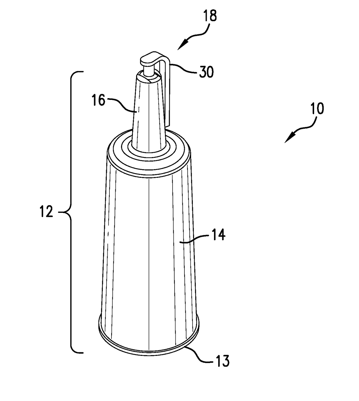
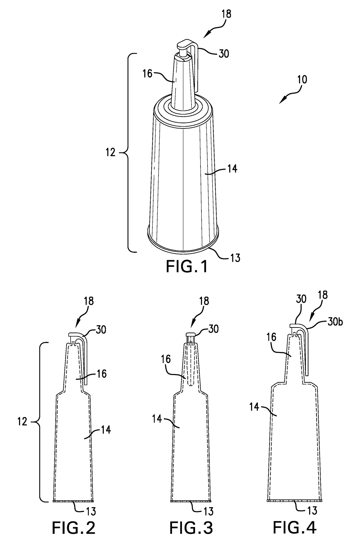
[0037]With reference now to the drawings, and in particular to FIGS. 1-19, embodiments of applicator assemblies embodying the principles and concepts of the present invention will be described.

[0038]An embodiment of an applicator assembly, which is generally designated by reference numeral 10, is shown in FIGS. 1-5. The applicator 10 is a one-piece element that includes a reservoir body 12 that is defined by a housing 14 and a neck 16 that extends from the housing 14 and a cap 18 that is integrally formed with the reservoir body 12 and that extends from a distal end 15 (see FIG. 8) of the neck 16. After introducing contents (e.g., liquid, gel, etc.) into the reservoir body 12 during manufacturing, an end 13 of the reservoir body 12, opposite that of the distal end of the neck 16, can be heated to seal the contents within the reservoir body 12. It is noted that the size of the reservoir body 12 is not limited to a specific size, but rather can vary depending on the volume of contents...


PUM


Abstract

An applicator assembly, a method of assembly of the applicator and a method of use of the applicator. The applicator assembly includes a reservoir body, a neck that extends from the reservoir body and includes an exposable opening at a distal end thereof and a shroud that extends from the distal end about the exposable opening and a cap that is integrally formed with and releasably fixed to the distal end of the neck, fully encompassing the opening in the neck and sealing the reservoir body.

Description

FIELD OF THE INVENTION[0001]This invention relates generally to an applicator and more specifically to an applicator that includes a reservoir body and cap that is formed integral with the reservoir body and that is separable from the reservoir body to allow for a release and dispersion of contents housed within the reservoir body of the applicator.BACKGROUND OF THE INVENTION[0002]Applicators designed for various purposes to deliver liquid, gel, or the like are well known. Such applicators typically include a housing (i.e., a tube or reservoir body) that has at least an opening formed in one end thereof and a cap that can be secured to the housing to seal the opening by screwing, snapping or sliding the cap over an end of the housing with the opening formed therein to seal the applicator. Alternatively, known applicators may include a cap that is permanently fixed to a body of the applicator to aid in dispensing contents housed therein by depressing the cap and / or articulating the c...

Claims


Application Information

Patent Timeline
IPC IPC(8): B65D47/10B65D1/09B65D1/02
CPCB65D47/106B65D1/0238B65D1/095
Inventor OLIVEIRA, VITORIKEGAMI, TAKESHI
Owner HARTZ MOUNTAIN
Learn More