Shortened Slit Lamp Microscope

a shortened, slit lamp technology, applied in the field of slit lamp microscopes, can solve the problems of preventing patients from being able to reach the chin and forehead rest, sacrificing the functions, features and usability of the conventional slit lamp, and inability to support many of the peripheral accessories available, so as to achieve comfort. the effect of us

Inactive Publication Date: 2018-10-25
XUE HAIXIN
View PDF2 Cites 4 Cited by
  • Summary
  • Abstract
  • Description
  • Claims
  • Application Information

AI Technical Summary

Benefits of technology

[0006]The present invention can also provide a slit lamp microscope or eye examination device having a chin rest, which can be comfortably used with large or obese patients, including those over 300 pounds, and even 400 pounds and over. Embodiments of the eye examination device in the present invention can include eye examination optics for examining a patient's eyes. A chin rest assembly can accept the patient's head and hold or maintain the patient's head in a fixed stable position. The chin rest assembly can include two spaced apart upright posts for securing to a table. A forehead rest member can be secured to the two upright posts at an upper region or end. A chin rest member can be secured to the two upright posts below the forehead rest member. The chin rest member can have a chin rest portion which extends forwardly relative to an upright plane extending between centers of the two upright posts and away from the eye examination optics, so that generally at most, only a front of the patient's face coincides with the upright plane when the patient's head engages the chin rest portion.
[0007]In particular embodiments, the two upright posts can be spaced apart at least about 349 mm apart. The chin rest member can include a bar having two ends that are angled forwardly to extend the chin rest portion forwardly therebetween. The chin rest portion can be extended forwardly relative to the upright plane by at least about 38.76 or 38 mm. In some embodiments, the chin rest portion can extend forwardly relative to the upright plane from about 18, 30 or 38 mm to about 70 mm. Moving the chin rest portion forwardly from about 18, 30, or 38 mm to about 70 mm, can move the front or front plane of the patient's face forward or in front of the upright plane and the upright posts. The height of eye examination components including the eye examination optics mounted on top of the table can be shortened, so that body parts of the patient, including protruding, large, obstructing, interfering or obese body parts, can be positioned below the table during examination, in a generally non-interfering manner.

Problems solved by technology

This is problematic when the patient body's shape and size falls outside of the average parameters or when the patient has limited body mobility, which can prevent the patient from being able to reach the chin and forehead rest while in a normal seated position.
However, these prior modifications sacrifice important functions, features and usability of the conventional slit lamp.
For example, the handheld and portable slit lamps currently available on the market only have one or two levels of magnification and generally require manual replacement of the ocular lenses to change between magnifications (versus up to five levels of magnification in a conventional slit lamp changeable via rotating drum), fewer filters than a conventional slit lamp, and inability to support many of the peripheral accessories available to conventional slit lamps for enhanced examination procedures (including, but not limited to, background illumination, wratten filtration, applanation tonometry, and specular microscopy); the suspended and table-free slit lamps have not yet been manufactured for the mass market, and as such are untested, but by the nature of their design are more challenging for the examiner to maneuver and operate than conventional slit lamps.
Typically, conventional slit lamp microscopes and associated chin rests used to examine a patient's eyes, are difficult to use for examining large or obese patients (for example over 300 pounds, or 200 pounds for a short person), due to the size and shape of the patient.
Although a large or obese patient's head and body can be pushed forward and forced by a doctor's assistant into the chin rest and against the equipment, this can be uncomfortable or painful for the patient.

Method used


Image

  • Shortened Slit Lamp Microscope
  • Shortened Slit Lamp Microscope
  • Shortened Slit Lamp Microscope

Examples


Embodiment Construction

[0040]A description of example embodiments of the invention follows.

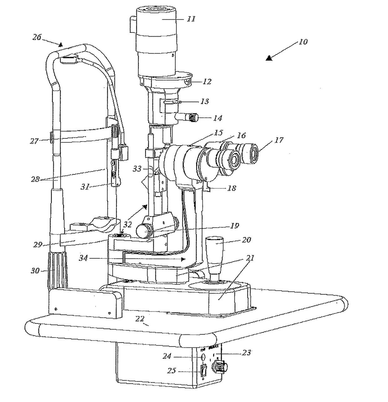
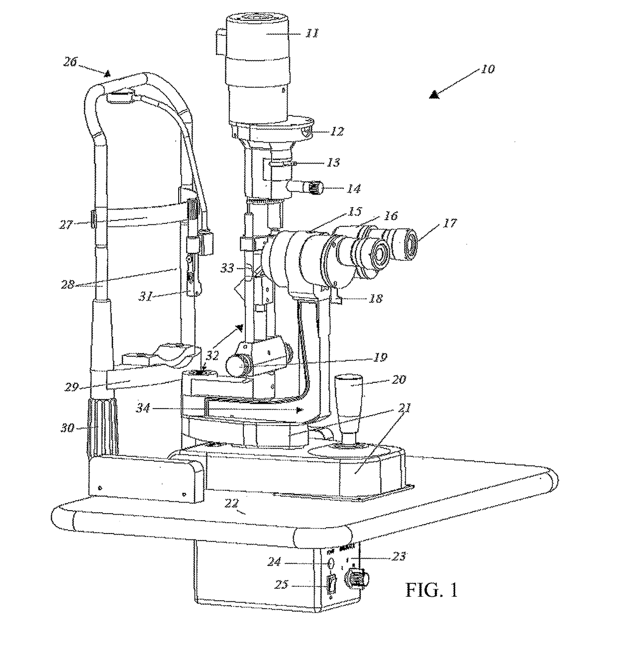
[0041]Referring now to the invention in more detail, in FIG. 1 there is shown a slit lamp microscope 10 which includes the lamp cap 11 with microscope light source, slit aperture display window 12, filter selection lever 13, slit aperture control knob 14, accessories mount 15, prism box 16, examiner's eyepiece 17, magnification changer 18, slit width control knob 19, joystick 20, joystick base 21, patient forehead and chin rest set 26, forehead strap 27, chin rest support bars 28, chin rest plate 29, chin rest elevation adjuster 30, fixation light 31, illumination tower 32, light reflecting mirror or member 33 and central ocular arm 34. There is also shown a tabletop 22 (which is connected to an adjustable instrument stand that is described below), power supply 23, power indicator light 24 and on / off switch 25.

[0042]In more detail, still referring to the invention of FIG. 1, the light reflecting mirror 33 shines a f...


PUM


Abstract

An eye examination device including eye examination optics for examining a patient's eyes. A chin rest assembly accepts the patient's head and maintains the patient's head in a fixed stable position. The chin rest assembly can comprise two spaced apart upright posts for securing to a table, with a forehead rest member being secured to the two upright posts at an upper end, and a chin rest member being secured to the two upright posts below the forehead rest member. The chin rest member can have a chin rest portion which extends forwardly relative to an upright plane extending between centers of the two upright posts and away from the eye examination optics, so that generally only a front of the patient's face coincides with the upright plane when the patient's head engages the chin rest portion.

Description

RELATED APPLICATION[0001]This application is a continuation-in-part of U.S. application Ser. No. 14 / 757,712 filed on Dec. 23, 2015, which claims the benefit of U.S. Provisional Application No. 62 / 183,928, filed on Jun. 24, 2015. The entire teachings of the above applications are incorporated herein by reference.BACKGROUND OF THE INVENTION[0002]Conventional slit lamp microscopes (U.S. Pat. No. D410,661; Jun. 8, 1999; Wolf, Theodor) are placed on a movable tabletop and positioned between the patient and examiner. The parts of the slit lamp include a joystick base controlled by the examiner, movable arms supporting the light source and optical components, and a chin rest and forehead rest for the patient to place his or her chin and forehead against while leaning forward to be examined. The height of a conventional slit lamp typically positions the base at the stomach region of the average patient and the focal point of the optical components at the eyes. This is problematic when the p...

Claims


Application Information

Patent Timeline
Patent Type & Authority Applications(United States)
IPC IPC(8): A61B3/00A61B3/135
CPCA61B3/0083A61B3/135A61B3/0008A61B3/0033A61B3/0075
Inventor XUE, HAIXIN
Owner XUE HAIXIN
Why Eureka
Try Eureka