
Inspection Unit For Photochromic Ophthalmic Lenses

a technology of ophthalmic lenses and inspection units, which is applied in the direction of measurement devices, structural/machine measurement, instruments, etc., can solve the problems of large-scale processes that are not well suited to making a small number of coated lenses, conventional inspection systems used in large-scale continuous lens manufacturing processes are simply too large and heavy to be used in an office setting,

Active Publication Date: 2018-10-18
TRANSITIONS OPTICAL INC
View PDF4 Cites 4 Cited by
  • Summary
  • Abstract
  • Description
  • Claims
  • Application Information

AI Technical Summary

Benefits of technology

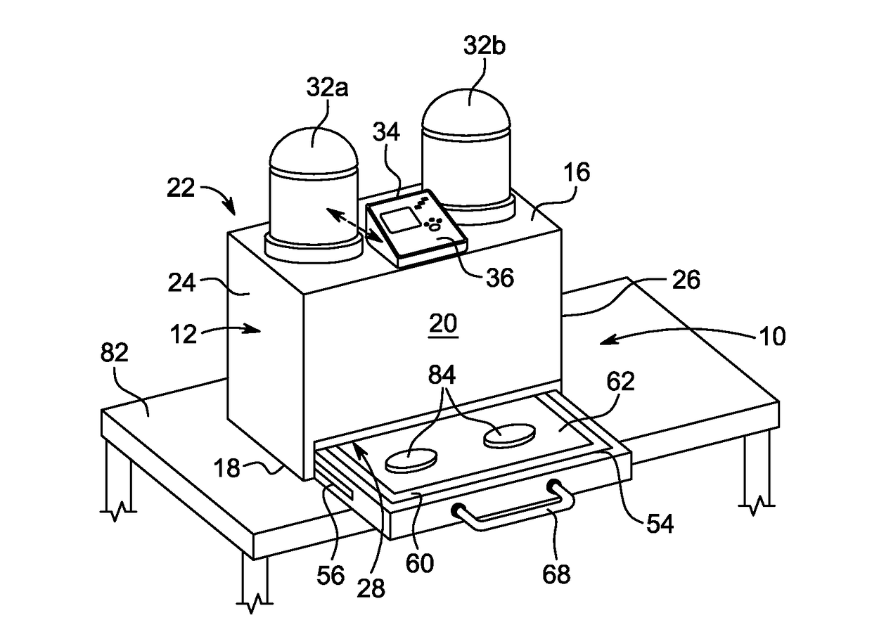
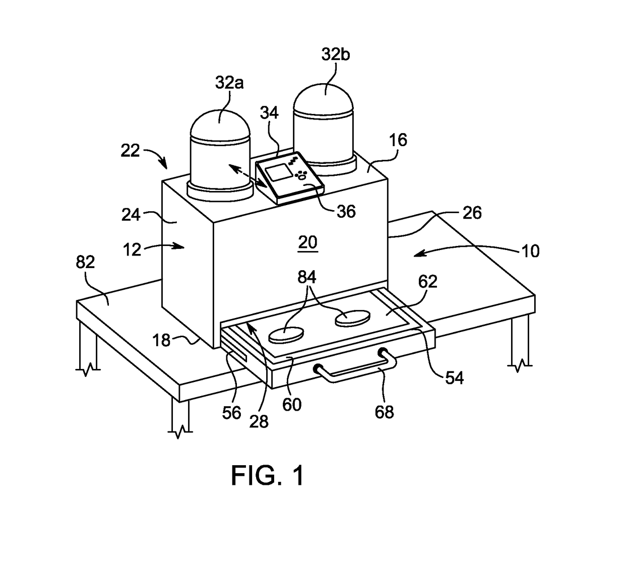
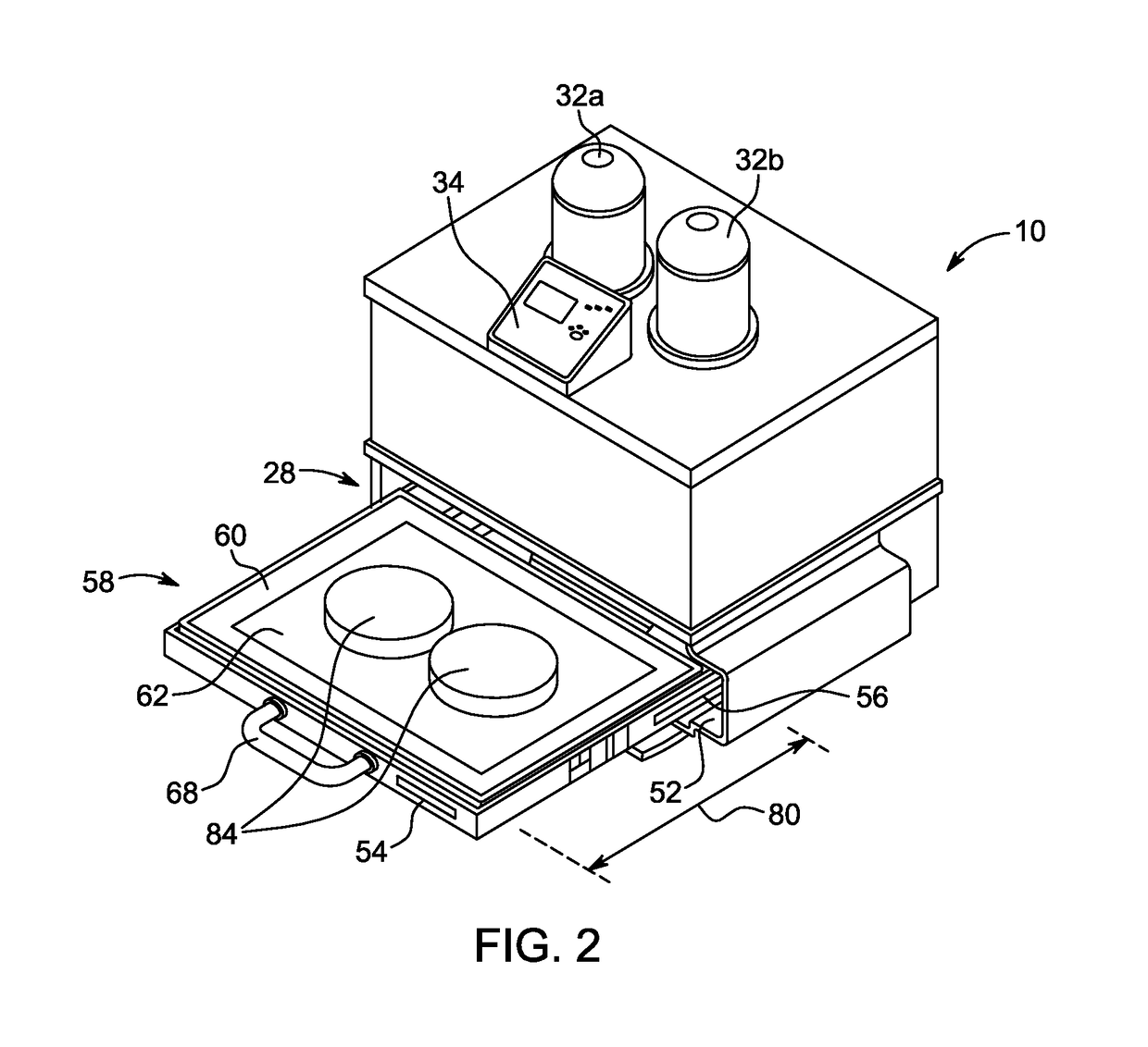
The patent describes an inspection unit for photochromic lenses that uses ultraviolet light to create color in the lens. The unit includes a housing, an inspection platform, and an ultraviolet light source. The method involves placing the lens on the inspection platform, inserting it into the housing, and withdrawing it for inspection. The technical effect is the ability to inspect photochromic lenses quickly and accurately in a batch manufacturing process.

Problems solved by technology

However, such large-scale processes are not well suited to making a small number of coated lenses having a wide variety of different coatings.
The inspection systems used in conventional large-scale continuous lens manufacturing processes would not be practical for these small-scale batch manufacturing processes.
The conventional systems are simply too large and heavy to be used in an office setting.

Method used


Image

  • Inspection Unit For Photochromic Ophthalmic Lenses
  • Inspection Unit For Photochromic Ophthalmic Lenses
  • Inspection Unit For Photochromic Ophthalmic Lenses

Examples


Embodiment Construction

[0016]Spatial or directional terms, such as “left”, “right”, “top”, “bottom”, and the like, relate to the invention as it is shown in the drawing figures. It is to be understood that the invention can assume various alternative orientations and, accordingly, such terms are not to be considered as limiting. All numbers used in the specification and claims are to be understood as being modified in all instances by the term “about”. All ranges disclosed herein are to be understood to encompass the beginning and ending range values and any and all subranges subsumed therein. The ranges set forth herein represent the average values over the specified range. The term “over” means “farther from the substrate”. For example, a second layer located “over” a first layer means that the second layer is located farther from the substrate than the first layer. The second layer can be in direct contact with the first layer or one or more other layers can be located between the second layer and the ...


PUM


Abstract

An inspection unit (10) for photochromic lenses (84) has a housing (12) defining an interior (14). At least one ultraviolet light source (32a, 32b) provides ultraviolet radiation into the housing interior (14). An inspection platform (54) is movable into and out of the housing interior (14) via at least one slide assembly (56). The inspection platform (54) includes a light table (58) having a translucent viewing area (62) and at least one inspection light source (64) located under the translucent viewing area (62).

Description

BACKGROUND OF THE INVENTIONField of the Invention[0001]This invention relates generally to the inspection of photochromic coatings and, more particularly, to a device and method for inspecting photochromic coatings applied to ophthalmic lenses in a batch coating process.Description of Related Art[0002]A photochromic material changes color when irradiated with ultra-violet (UV) radiation and then returns to its original color when the irradiation ceases. One useful application of this phenomenon is in the manufacture of ophthalmic lenses capable of darkening when exposed to sunlight.[0003]Conventional photochromic ophthalmic lenses are manufactured in large-scale, continuous manufacturing processes. In a “continuous process”, large numbers of related materials are produced at the same time. For example, the same photochromic coating composition is deposited onto the surfaces of numerous lenses to produce a supply of similarly coated photochromic lenses. The lenses have the same aesth...

Claims


Application Information

Patent Timeline
Patent Type & Authority Applications(United States)
IPC IPC(8): G01M11/02
CPCG01M11/0214G01M11/0285G01N21/8422G01N21/8803G01N21/958G01N2021/9583G01N2021/8427
Inventor KOENIG, II, JERRY L.
Owner TRANSITIONS OPTICAL INC
Learn More