
Image capture apparatus

a technology of image capture and apparatus, applied in the field of photoelectric devices, can solve the problems of small bubbles or partial cure of optical adhesive, inability to capture fingerprints by image sensors, and inability to complete fingerprint capture by image sensors, so as to reduce the recognition of image capture apparatus

Active Publication Date: 2018-10-11
GINGY TECH
View PDF1 Cites 3 Cited by
  • Summary
  • Abstract
  • Description
  • Claims
  • Application Information

AI Technical Summary

Benefits of technology

The technical effect of this patent is to improve the image recognition of an image capture apparatus by preventing signal light beams from being totally reflected before entering the image capture device. This is achieved by using a light emitting portion with multiple enhanced transmission microstructures and an image capture device disposed on the second side of a light guide element corresponding to the position of the microstructures.

Problems solved by technology

However, due to the process constraints, the optical adhesive may have small bubbles or may not be completely cured.
Thus, the fingerprint captured by the image sensor will not be completed, and impair the recognition.

Method used


Image

  • Image capture apparatus
  • Image capture apparatus
  • Image capture apparatus

Examples


Embodiment Construction

[0023]Reference will now be made in detail to the exemplary embodiments of the instant disclosure, examples of which are illustrated in the accompanying drawings. Wherever possible, the same reference numbers are used in the drawings and the description to refer to the same or like parts.

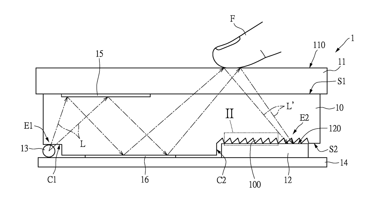
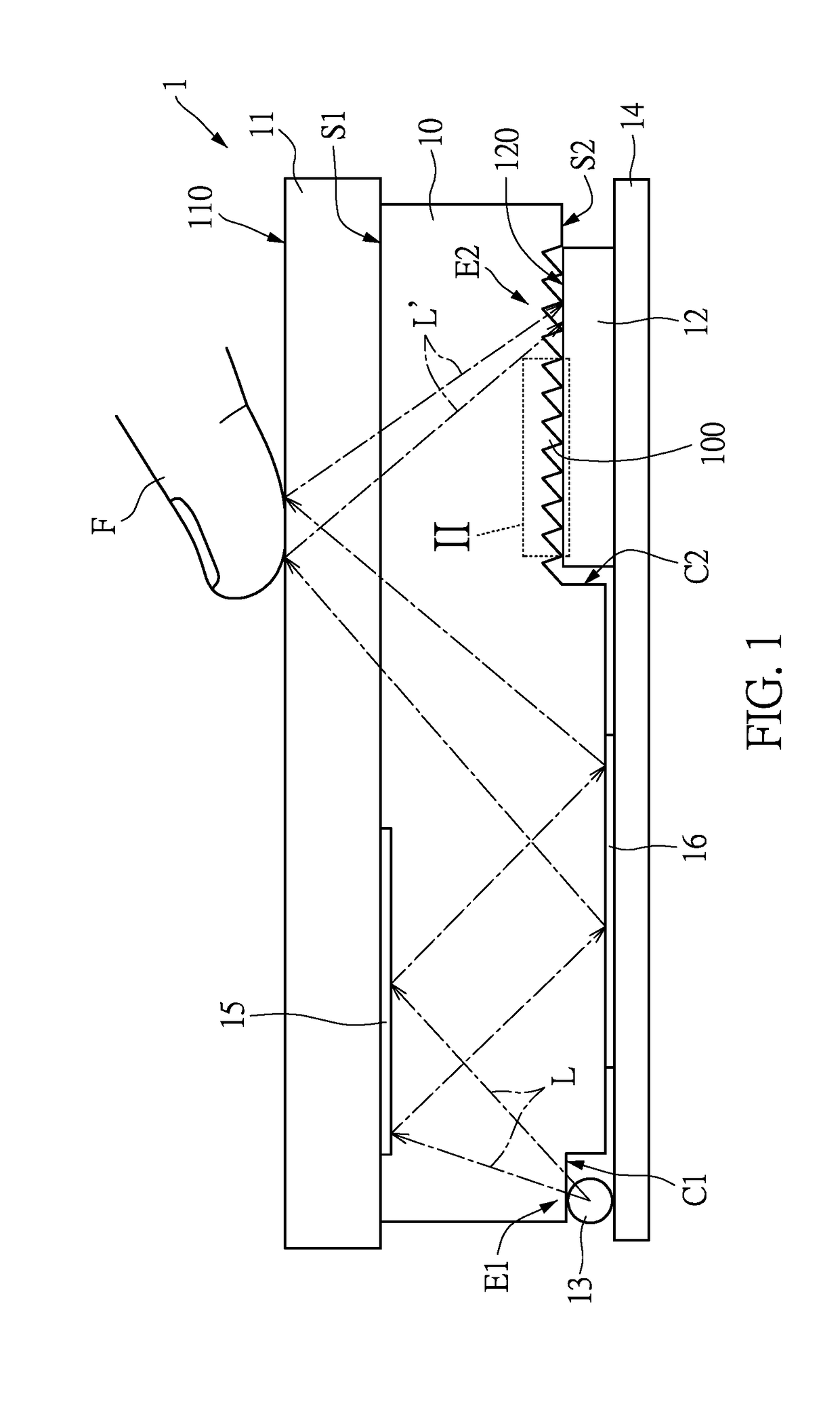
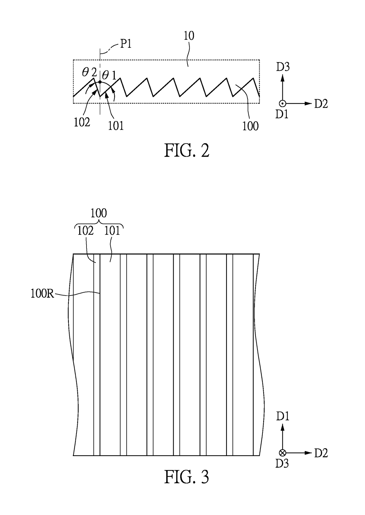
[0024]Please refer to FIG. 1 and FIG. 2. FIG. 1 shows a cross-sectional view of one embodiment of the image capture apparatus of the present disclosure, and FIG. 2 is a partial enlarged view depicting area II of FIG. 1 of one embodiment of a plurality of enhanced transmission microstructures of the present disclosure.

[0025]An exemplary embodiment of the present disclosure provides an image capture apparatus 1. The image capture apparatus 1 is used in an environmental medium. In an embodiment, the above-mentioned environmental medium can be gas, water, or other kinds of environmental mediums. The image capture apparatus 1 can used to capture an image of an object F for identification, the above-menti...


PUM


Abstract

An image capture apparatus including a light guide element, an image capture device and a light emitting device. The light guide element has a first side, a second side and a light emitting portion located at the second side. The light emitting portion includes a plurality of enhanced transmission microstructures. The image capture device is disposed on the second side of the light guide element corresponding to the position of the enhanced transmission microstructures. A light beam, which is generated by the light emitting device and transmitted at least by the light guide element, is totally reflected to form a signal light beam. Thereafter, the signal light beam passes through the enhanced transmission microstructures and then is received by the image capture device.

Description

CROSS REFERENCE TO RELATED APPLICATION[0001]This application is a continuation-in-part application of and claims the priority benefit of a prior application Ser. No. 15 / 588,700, filed on May 8, 2017, now pending, which claims the priority benefits of U.S. provisional application Ser. No. 62 / 371,230, filed on Aug. 5, 2016, U.S. provisional application Ser. No. 62 / 413,974, filed on Oct. 27, 2016, and China application serial no. 201720260844.9, filed on Mar. 17, 2017. This application is also a continuation-in-part application of and claims the priority benefit of a prior application Ser. No. 15 / 399,704, filed on Jan. 5, 2017, now pending, which claims the priority benefits of U.S. provisional application Ser. No. 62 / 371,230, filed on Aug. 5, 2016, U.S. provisional application Ser. No. 62 / 413,974, filed on Oct. 27, 2016, and Taiwan application serial no. 105135846, filed on Nov. 4, 2016. This application is also a continuation-in-part application of and claims the priority benefit of ...

Claims


Application Information

Patent Timeline
Patent Type & Authority Applications(United States)
IPC IPC(8): G06K9/00F21V8/00G02B27/09H01L27/146
CPCG06K9/0004G02B6/0031G02B27/0977G06K9/00087H01L27/14629G02B2006/12107G02B2006/12138G06V40/1318G06V40/1365
Inventor HUANG, CHENG-JYUN
Owner GINGY TECH
Learn More