
Design method for choosing spectral selectivity in multispectral and hyperspectral systems

a design method and hyperspectral system technology, applied in the field of parameterizing a weighting function, can solve the problems of lagging spectral selectivity/differentiation, affecting the performance of the system, and a large set of spectral channels can be problematic for tasks, etc., to achieve rapid learning and high adaptability

Inactive Publication Date: 2018-10-11
THE UNITED STATES OF AMERICA AS REPRESENTED BY THE SECRETARY OF THE NAVY
View PDF0 Cites 5 Cited by
  • Summary
  • Abstract
  • Description
  • Claims
  • Application Information

AI Technical Summary

Benefits of technology

The invention is a method for designing spectral filters that can be tuned to different response objectives. It uses a global optimizer and a unique coding method to search the space of filter parameters and reduce the number of parameters needed. The method is highly adaptable and can be applied to a variety of imaging objectives. Additionally, it allows for the rapid learning of optimal filters and ensures conformance to industry manufacturing constraints. Overall, the method maintains significant design generality while requiring fewer parameters, allows for consistent convergence to high-quality solutions, and is highly adaptable to various imaging objectives.

Problems solved by technology

For material detection and / or identification, these familiar color cameras typically lack spectral selectivity / differentiation; that is, dividing the incoming light into three bands does not sufficiently sample the spectra, Multi- and hyperspectral imagers seek to generate finer samplings of the spectrum (N-tuples, where N is the number of bands) such that useful identifying information about the underlying materials is not averaged out by the sampling process.
At some point, however, liner spectral resolution provides diminishing returns because nearby bands can be closely correlated over a given spectral interval.
In addition, a larger set of spectral channels can be problematic for tasks such as classification because the dimensionality of the spectral signature is large and subject to the “curse of dimensionality.”
For example, discrete, binary parameterizations yield combinatorial optimizations that are generally more difficult to solve than continuous parameterizations.

Method used


Image

  • Design method for choosing spectral selectivity in multispectral and hyperspectral systems
  • Design method for choosing spectral selectivity in multispectral and hyperspectral systems
  • Design method for choosing spectral selectivity in multispectral and hyperspectral systems

Examples


Embodiment Construction

[0023]In the course of solving the above-mentioned optimization problem. Applicants developed the four major components that make up the general spectral selection problem and the weighting function (filter) parameterization / encoding according to an embodiment of the invention. They realized their solution's applicability to a wide range of device designs, such as manufacturing or digital designs for photonic systems, electrical circuits, digital filters, acoustic filters, electric filters, or electromagnetic filters.

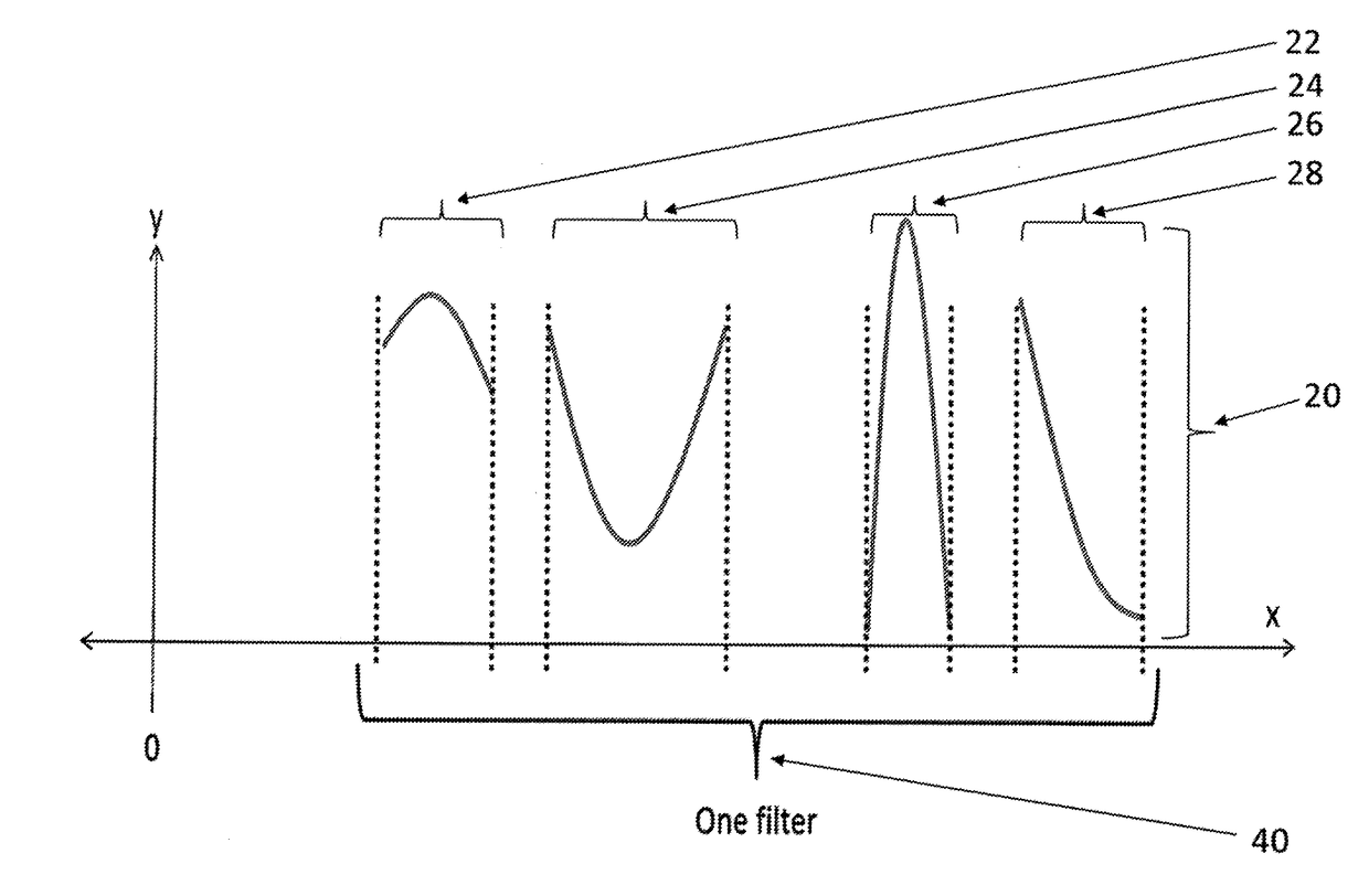
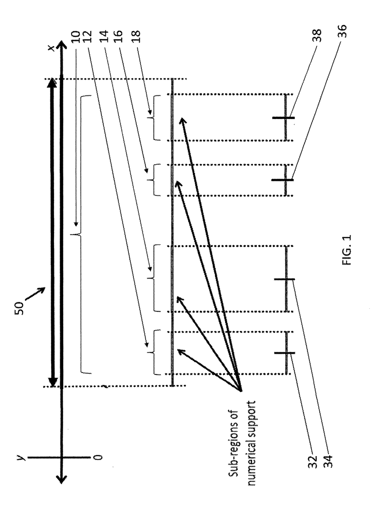
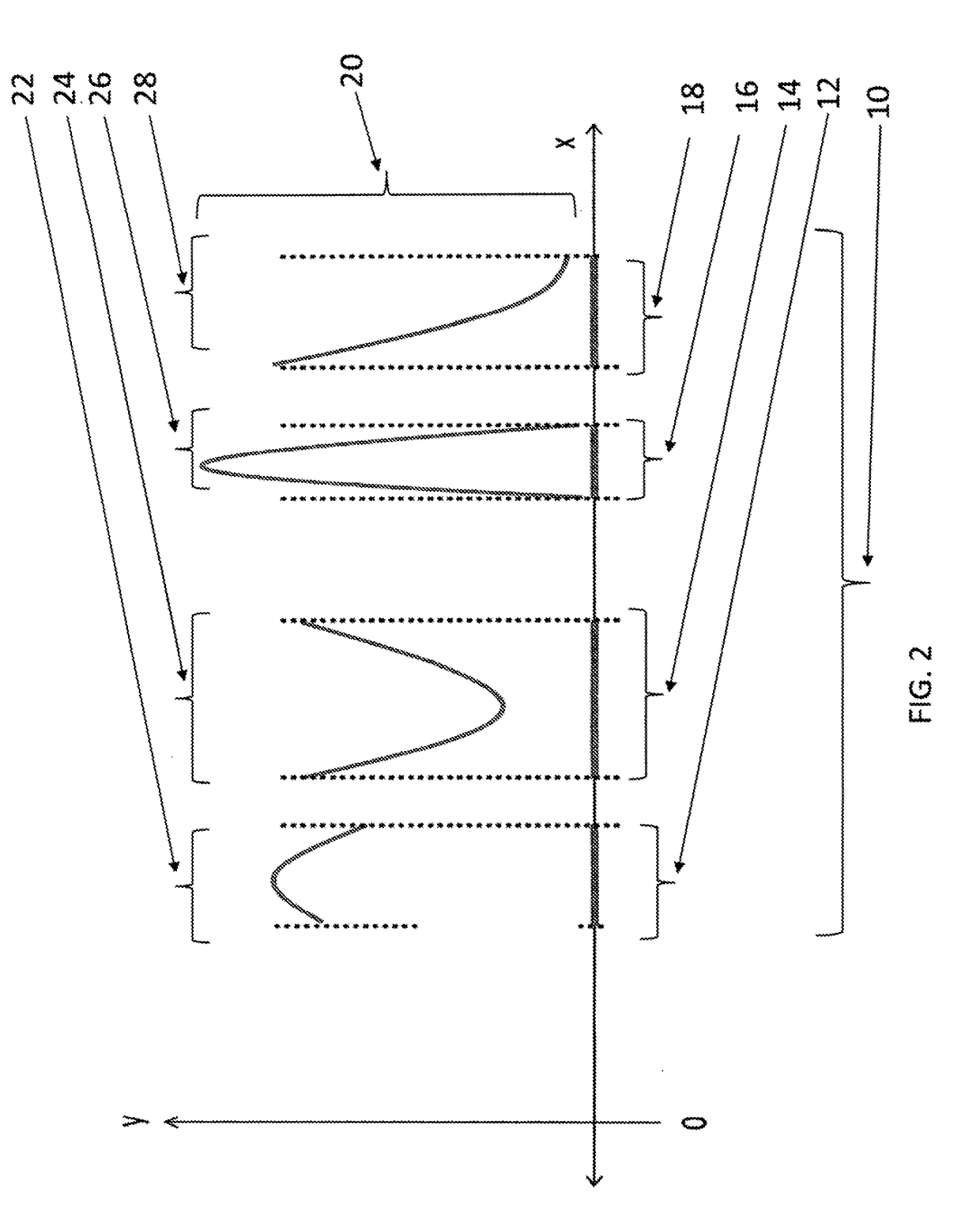
[0024]An embodiment of the invention includes a method and is described as follows with reference to FIGS. 1-3. A first plurality 10 of numerical support sub-regions is provided, as shown by way of illustration in FIG. 1. Only four numerical support sub-regions 12, 14, 16, 18 are shown for ease of understanding. One of ordinary skill in the art will readily appreciate that practical embodiments of the invention include less than four numerical support or greater than fo...


PUM


Abstract

A method, wherein a first plurality of numerical support sub-regions is provided. A manufacturing constraint and a response objective are provided. A first plurality of shapes for the first plurality of numerical support sub-regions is generated. Each shape of the first plurality of shapes corresponds to a respective numerical support sub-region. Each shape corresponds to a respective function of numerical support within the respective numerical support sub-region. Each respective function of numerical support uses: a first respective center number corresponding to each numerical support sub-region, the first respective center number depending on the at least one manufacturing constraint, a first respective Beta distribution, a first respective alpha Beta distribution shape parameter constrained by the at least one manufacturing constraint, and a first respective beta Beta distribution shape parameter constrained by the at least one manufacturing constraint. A highest-rated device response is generated using the first plurality of shapes.

Description

CROSS-REFERENCE TO RELATED APPLICATIONS[0001]The present application claims priority to U.S. Provisional Patent Application Ser. No. 62 / 481,803, which was filed on Apr. 5, 2017 and is incorporated herein by reference.[0002]BACKGROUND OF THE INVENTIONField of the Invention[0003]This invention relates in general to a method for parameterizing a weighting function for a manufacturing or digital design response target / objective, and in particular to a method for parameterizing a weighting function for a manufacturing or digital design response target / objective of a photonic system, an electrical circuit, a digital filter, an acoustic filter, an electrical filter, or an electromagnetic filter.Description of the Related Art[0004]Imaging systems capture-spectral information about different objects in a scene by measuring spectral response within the scene using materials with certain spectral sensitivities. For example, ubiquitous color cameras distinguish red stop signs from green trees. ...

Claims


Application Information

Patent Timeline
Patent Type & Authority Applications(United States)
IPC IPC(8): G06F17/50G06F17/18
CPCG06F17/50G06F17/18G06F2217/12G06F2217/06G06F30/00G06F2111/04G06F2119/18Y02P90/02
Inventor OLSON, COLINDOSTER, TIMOTHY
Owner THE UNITED STATES OF AMERICA AS REPRESENTED BY THE SECRETARY OF THE NAVY
Learn More