Construction vehicle tire

a technology for construction vehicles and tires, applied in the field of construction vehicle tires, can solve the problems of not being not always able to reduce compression strain effectively, and achieve the effect of suppressing compression deformation near the position of the minimum value a

Inactive Publication Date: 2018-10-11
BRIDGESTONE CORP
View PDF4 Cites 0 Cited by
  • Summary
  • Abstract
  • Description
  • Claims
  • Application Information

AI Technical Summary

Benefits of technology

The present invention aims to provide a construction vehicle tire that can reduce compression strain in the folded portion of the carcass and improve durability of the bead portion, even in situations where there is a large lateral force input during use.

Problems solved by technology

That is, an inflection point of the carcass folded portion with respect to the compression strain in a state in which the lateral force is large is shifted from an inflection point of the carcass folded portion in a state in which the lateral force is small, and thereby it is found that the compression strain might not be always reduced effectively.
Specifically, in a state in which the lateral force is large, a position of the inflection point is moved toward an end portion of the carcass folded portion at the outer side in the tire radial direction, and therefore the compression strain might not be reduce effectively in a positional relation between the carcass body portion and the carcass folded portion in the conventional construction vehicle tire described above.

Method used


Image

  • Construction vehicle tire
  • Construction vehicle tire
  • Construction vehicle tire

Examples


first embodiment

[0025]At first, a construction vehicle tire according to a first embodiment of the present invention will be described with reference to drawings.

(1) Schematic Configuration of Construction Vehicle Tire

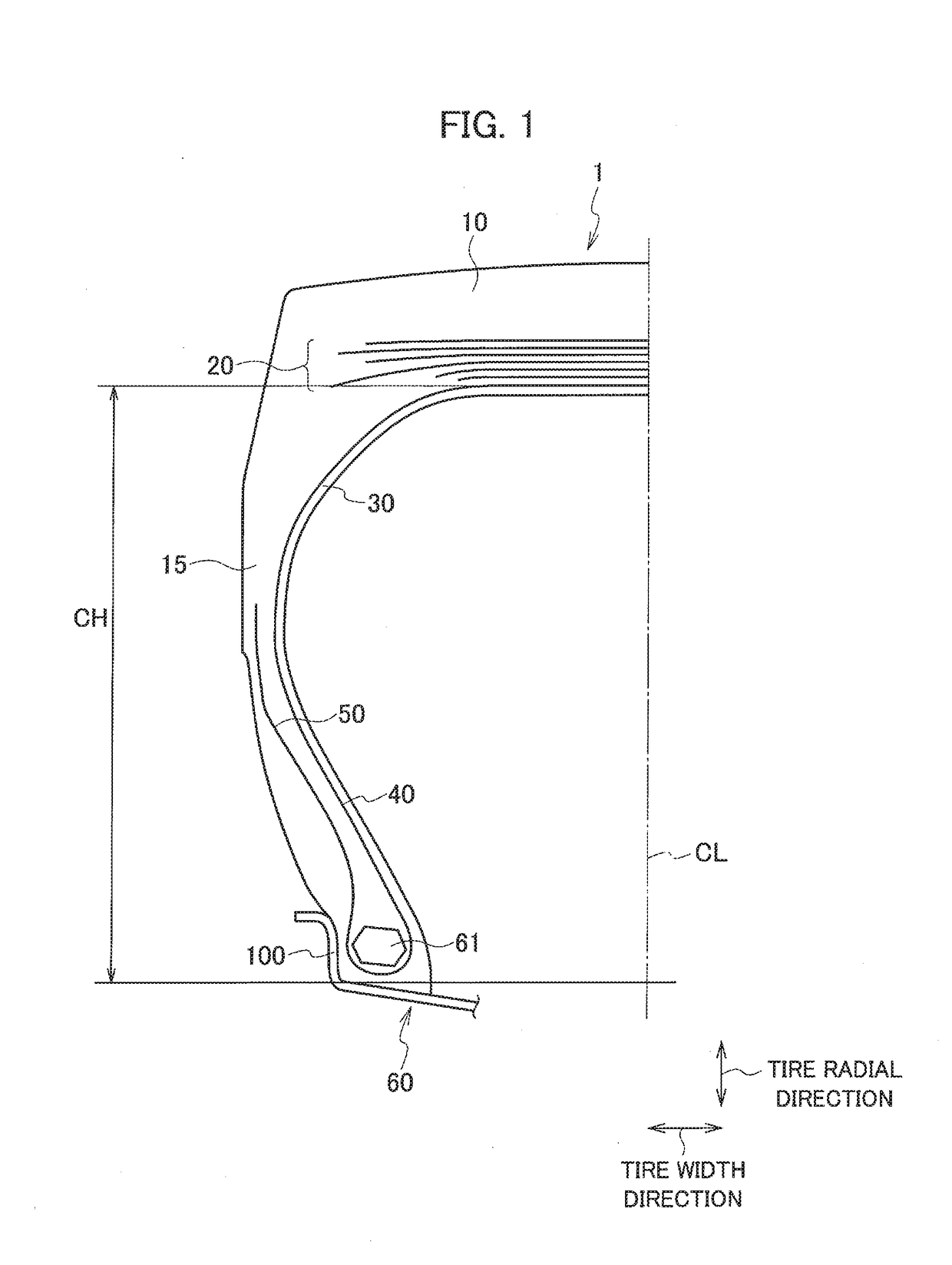
[0026]FIG. 1 is a cross-sectional view along a tire width direction and a tire radial direction illustrating a part of a construction vehicle tire 1 according to the present embodiment. The construction vehicle tire 1 is formed symmetry in a lateral direction with respect to a tire equatorial line CL.

[0027]The construction vehicle tire 1 is preferably used as a construction vehicle tire used in, for example, a dump truck, an articulate dump truck, or a wheel loader that travels on crushed stones, or in a mine or a dam construction site. As shown in FIG. 1, the construction vehicle tire 1 is provided with a tread portion 10 that contacts with a road surface, a side wall portion 15 continued to the tread portion 10 and arranged at an inner side in the tire radial direction with respect ...

second embodiment

[0044]Next, a second embodiment of the present invention will be described. Hereinafter, a difference from the construction vehicle tire 1 according to the first embodiment described above will be mainly described, and therefore a description of a configuration similar to that in the construction vehicle tire 1 will be omitted as needed.

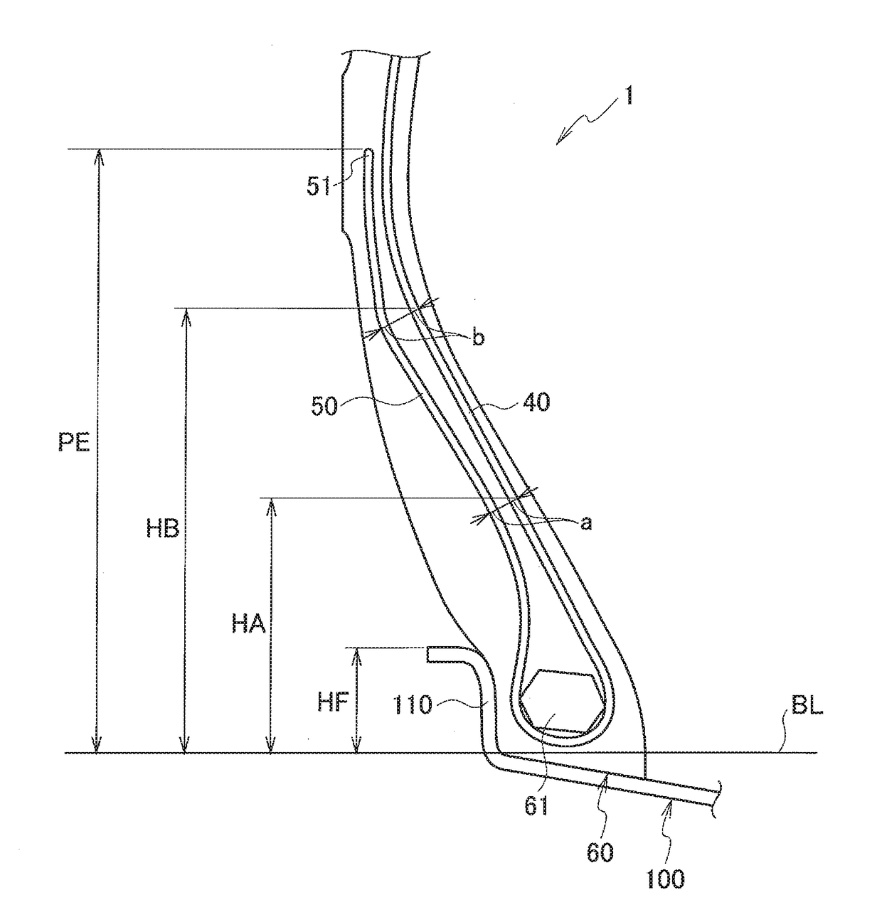
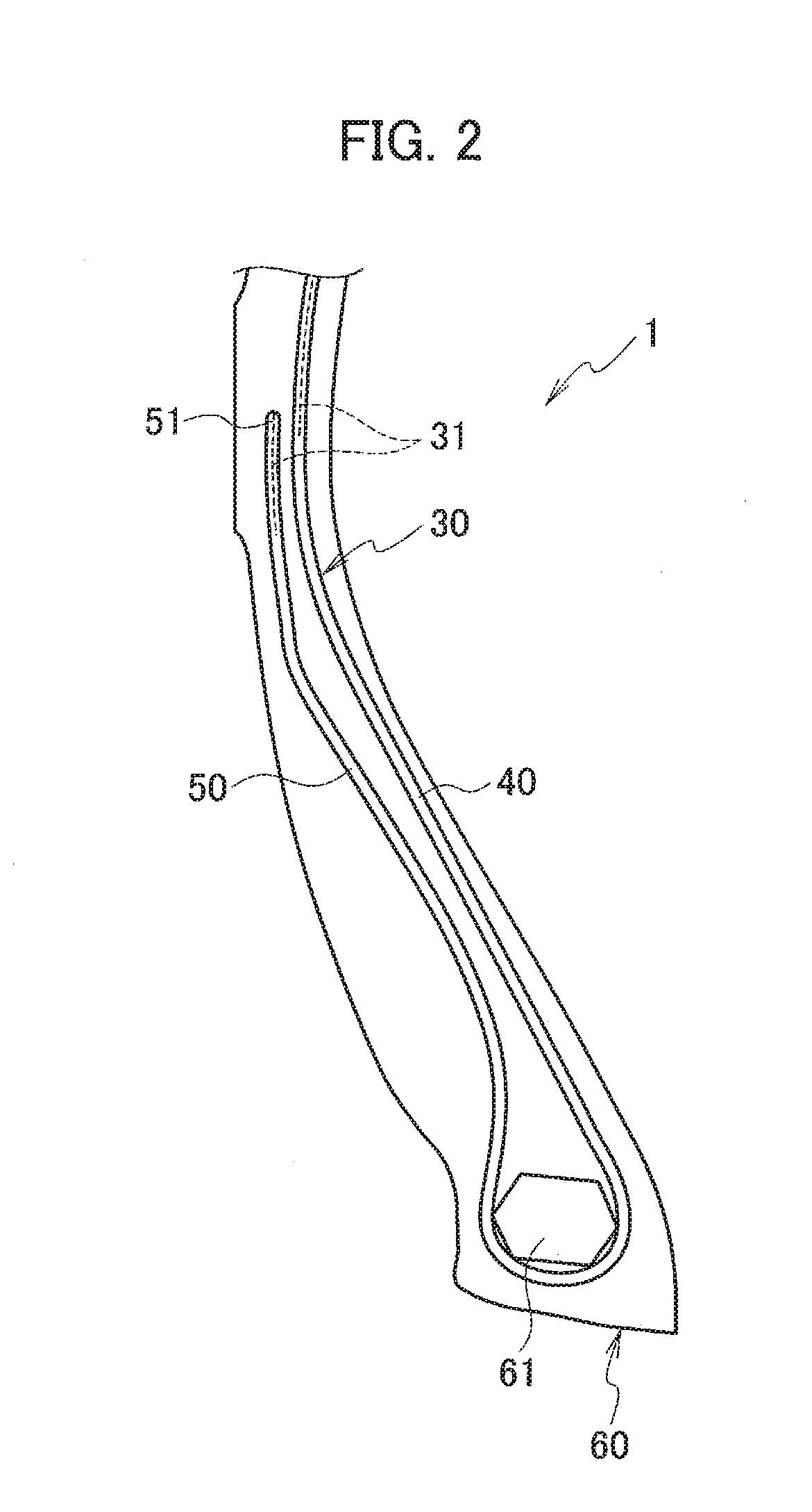
[0045]FIG. 5 is an enlarged cross-sectional view of a bead portion 60 of a construction vehicle tire 1A according to the present embodiment. Each configuration of a tread portion 10 and a belt layer 20 of the construction vehicle tire 1A is similar to that of the construction vehicle tire 1. As shown in FIG. 5, in the construction vehicle tire 1A, a shape (positional relation) of a carcass folded portion 50 is different from that in the construction vehicle tire 1.

[0046]FIG. 6 shows a specific positional relation of a carcass body portion 40 and the carcass folded portion 50 of the construction vehicle tire 1A. As shown in FIG. 6, when the constructi...


PUM


Abstract

To provide a construction vehicle tire capable of reducing compression strain generated in a carcass folded portion and improving durability of a bead portion even in a state closer to an actual use environment in which large lateral force is input. In a construction vehicle tire (1) according to the present invention, when mounted to a wheel rim (100), a height (HA) of a carcass cord (31) of a carcass body (40) corresponding to the minimum value a from a base line (BL) of the wheel rim (100), a height (HB) of the carcass cord (31) of the carcass body portion (40) corresponding to the maximum value b from the base line (BL), and a flange height (HF) of the wheel rim (100) from the base line (BL) fulfill relations of 1.2 HF≤HA≤2.5 HF, 2.6 HF≤HB≤3.5 HF, and 1.10≤b / a<1.40.

Description

TECHNICAL FIELD[0001]The present invention relates to a construction vehicle tire, in particular, a construction vehicle tire in which durability of a bead portion is improved.BACKGROUND ART[0002]A large load is applied to a construction vehicle tire mounted to a construction vehicle that travels on an uneven road surface in a construction site and has a large loading mount, and therefore it is especially important to improve durability of a bead portion in order to lengthen a tire life.[0003]In the construction tire used in the environment described above, a large compression strain is repeatedly generated in a carcass folded portion folded at a bead core from a carcass body portion toward an outer side in a tire radial direction, and therefore a method for reducing the compression strain is proposed. For example, a method for optimizing a distance between the carcass body portion and the carcass folded portion, specifically a distance between carcass cords in a section along a tir...

Claims


Application Information

Patent Timeline
IPC IPC(8): B60C15/00
CPCB60C15/0054B60C2200/065B60C15/0009B60C15/0063B60C2015/009
Inventor KITORA, ATSUSHI
Owner BRIDGESTONE CORP
Why Eureka
Try Eureka