Tool-holder head, transport carriage and methods for mounting and removing a tool for a unit for converting a flat substrate

a technology for flat substrates and transport carriages, which is applied in the direction of box making operations, container making machinery, mechanical working/deformation, etc., can solve the problems of time-consuming and laborious cylinder changing operations, numerous tool changes may be necessary, and the cylinder cannot be changed very quickly, so as to reduce the risk of collision with tools, and improve the safety of handling the transport carriage in the factory

Active Publication Date: 2018-10-11
BOBST MEX SA
View PDF57 Cites 0 Cited by
  • Summary
  • Abstract
  • Description
  • Claims
  • Application Information

AI Technical Summary

Benefits of technology

This invention is a transport carriage that allows for easy mounting and dismounting of rotary tools without additional manipulations. The carriage includes a tool-holder head and a lifting device that can raise or lower the head. This makes it safer to handle and transport heavy tools. Additionally, the positioning of the rotary tools along the bearing axis of the conversion unit is easier, reducing the risk of collisions and the number of operations required. The lifting device also helps to balance the load, reducing the risk of the carriage becoming unbalanced by the rotary tools.

Problems solved by technology

The cylinder changing operations have been found to be time-consuming and tedious.
Because of its fairly high weight, a cylinder cannot be changed very quickly.
Moreover, numerous tool changes may be necessary to obtain a very large number of boxes that are different from one another.
These tools have to be ordered a long time in advance, which is becoming incompatible with the production changes that are currently required.
In addition, tools are relatively expensive to produce and only become cost-effective with an extremely large output.
However, the operations of loading and exchanging rotary tools in the conversion units remain tricky for operators, notably because of the mounting precision demanded in the unit and of the high weight of these tools.

Method used


Image

  • Tool-holder head, transport carriage and methods for mounting and removing a tool for a unit for converting a flat substrate
  • Tool-holder head, transport carriage and methods for mounting and removing a tool for a unit for converting a flat substrate
  • Tool-holder head, transport carriage and methods for mounting and removing a tool for a unit for converting a flat substrate

Examples


Embodiment Construction

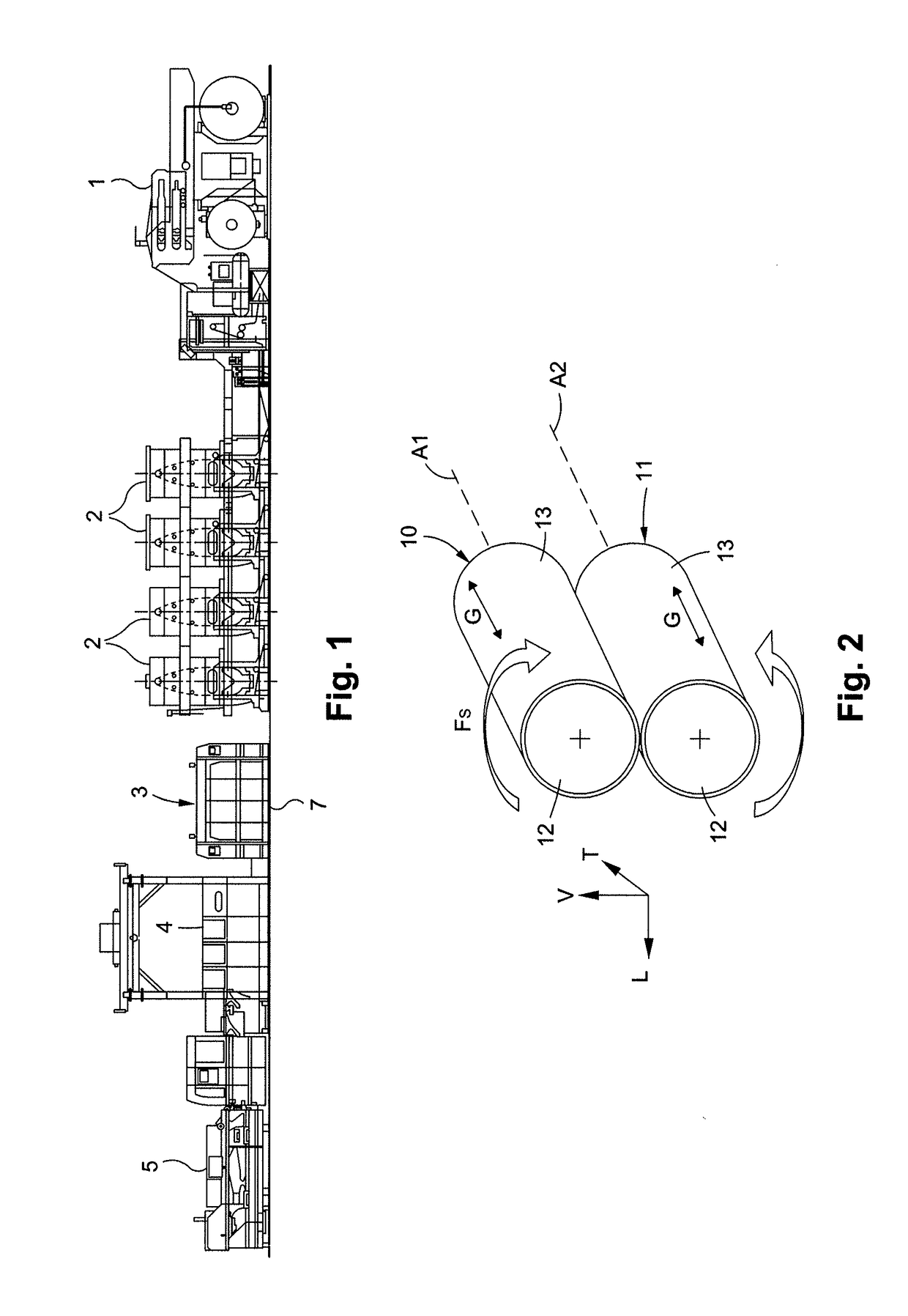
[0056]A conversion line for converting a flat substrate, such as a flat cardboard or a continuous web of paper wound on a reel, makes it possible to carry out various operations and obtain packaging such as folding boxes. As shown in FIG. 1, the conversion line comprises, disposed one after another in the order of passage of the flat substrate, an unwinding station 1, several printer units 2, one or more embossing units in series followed by one or more scoring units in series 3, followed by a rotary cutting unit 4 or platen die-cutting unit, and a station 5 for receiving the manufactured objects.

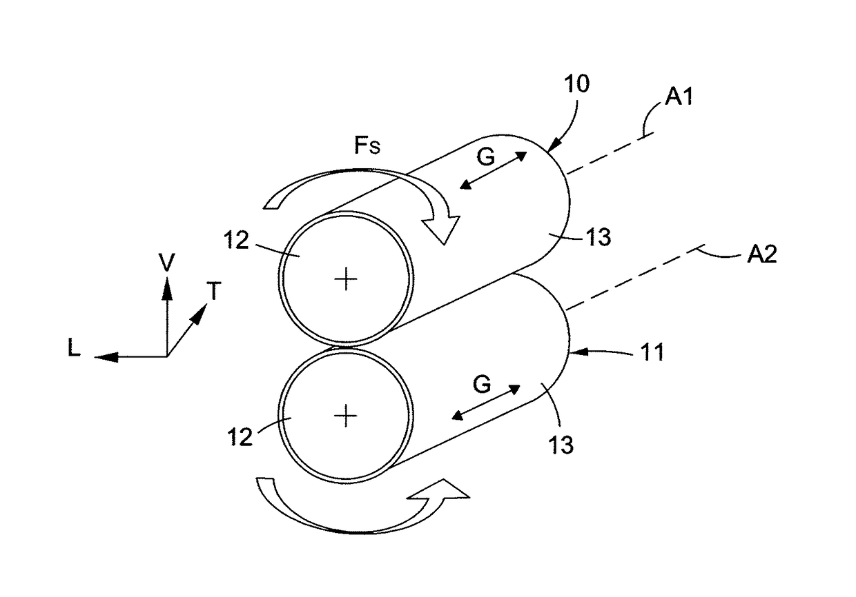
[0057]The conversion unit 7 comprises an upper rotary tool 10 and a lower rotary tool 11, which modify the flat substrate by printing, embossing, scoring, cutting, ejection of scrap, etc., in order to obtain packaging.

[0058]The rotary tools 10 and 11 are mounted parallel to one another in the conversion unit 7, one above the other, and extend in the transverse direction T, which is also the...


PUM


Abstract

A tool-holder head for a carriage for transporting rotary tools of a unit for converting a flat substrate, which includes an upper port (29) and a lower port (30) arranged one above the other and intended to receive a front end of an upper rotary tool (10) and a front end of a lower rotary tool (11), respectively.

Description

CROSS-REFERENCE TO RELATED APPLICATION[0001]The present application is a 35 U.S.C. §§ 371 national phase conversion of PCT / EP2015 / 025090, filed Nov. 26, 2015, which claims priority of European Patent Application No. 14020102.1, filed Dec. 4, 2014, the contents of all of which are incorporated herein by reference. The PCT International Application was published in the French language.FIELD OF THE INVENTION[0002]The present invention relates to a tool-holder head, intended for a carriage for transporting rotary tools, for a unit for converting a flat substrate. The invention relates to a transport carriage provided with a tool-holder head for a unit for converting a flat substrate. The invention also relates to a method for mounting a tool in a unit for converting a flat substrate and to a method for removing a tool from a unit for converting a flat substrateBACKGROUND[0003]A machine for converting a substrate is intended for the production of packaging. In this machine, an initial fl...

Claims


Application Information

Patent Timeline
Patent Type & Authority Applications(United States)
IPC IPC(8): B31F1/07
CPCB31F1/07B31F2201/0753B31F2201/0776B31B50/25B31B50/16B31B50/146B31B50/256B31B50/88
Inventor ROBADEY, PIERRE
Owner BOBST MEX SA
Why Eureka
Try Eureka